Removal and installation of an inlet collector
Removing the intake manifold
1. Disconnect the negative battery terminal.
2. Remove the air filter unit.
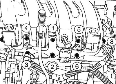
3. Loosen the bolt (1) oil filler neck mountings.
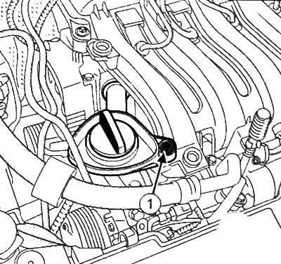
4. Remove the oil filler neck.
5. Disconnect the oil vapor vent (2).
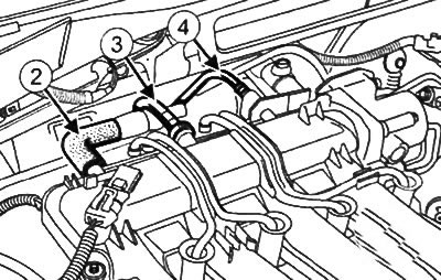
6. Disconnect the brake booster vacuum line (3).
7. Disconnect the gasoline vapor ventilation pipe (4).
8. Disconnect intake manifold vacuum sensor connector (5).
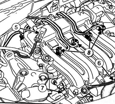
9. Disconnect the intake air temperature sensor connector (6).
10. Disconnect the fuel injector connectors.
11. Disconnect the throttle connector.
Attention: When working with fuel cells, do not smoke and do not allow the use of open flames in the workplace. Since fuel leaks are possible when fuel line connectors are disconnected, take measures to protect surrounding components from fuel spillage.
12. Disconnect the fuel supply line from the fuel rail (7).
13. Disconnect spark plug wires (8).
Caution: When disconnecting spark plug wires, pull on the connectors, not on the wires.
14. Remove the fuel rail.
15. Disconnect the high-voltage wires of the spark plugs and the oil dipstick from the intake manifold.
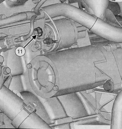
16. Disconnect the power terminal (11) from the starter.
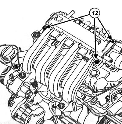
17. Loosen the bolts (12) intake manifold from the rocker cover.
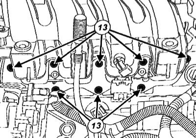
18. Loosen the bolts (13) intake manifold from the cylinder head.
19. Remove the throttle valve with the storage chamber assembly.
20. Remove the intake manifold gasket.
Intake manifold installation
Note: Replace the intake manifold gasket with a new one after each removal.
Attention: To ensure the required tightness, the sealing surfaces must be clean, dry and free from grease (avoid any fingerprints).
1. Use a cleaning agent to clean and degrease the contact surfaces between the intake manifold and cylinder block and between the intake manifold and the rocker arm cover.
2. Install the intake manifold with a new gasket.
3. Apply LOCTITE FRENETANCH to the intake manifold-to-cylinder head bolts.
4. Tighten all intake manifold bolts to 6 Nm.
5. Tighten the intake manifold bolts in the sequence shown in the figure to a torque of 10 Nm.
6. Further installation is carried out in the reverse order of removal.
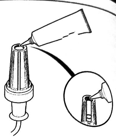
Note: When installing high voltage spark plugs, a bead of FLUORINATED GREASE must be applied (PART NO. 82 00 168 855) 2 mm in diameter along the inner edge of the cap.