
If one of the circuits of the working brake system fails, the second circuit is used, which ensures that the car stops with sufficient efficiency.
The hydraulic drive includes a vacuum booster and a dual-circuit rear brake pressure regulator.
The parking brake system has a cable drive to the rear wheel brakes.
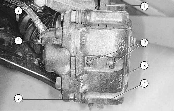
9.1. Front wheel brake: 1 - brake disc; 2 - brake pads; 3 - brake caliper; 4 - guide pads; 5 - caliper guide pin; 6 - air release valve; 7 - brake hose
Brake mechanism of the front wheel disc, with automatic adjustment of the gap between the pads 2 (pic. 9.1) and disk 1, with a floating bracket. The movable bracket is formed by a caliper 3 with a single-piston working cylinder. The shoe guide 4 is bolted to the steering knuckle. The movable bracket is bolted to guide pins 5 installed in the holes of the guide shoe. The guide pins are grease lubricated and protected by rubber boots. A piston with a sealing ring is installed in the cavity of the wheel cylinder. Due to the elasticity of this ring, an optimal clearance is maintained between the pads and the disc, the surface of which is protected by the brake shield. When braking, the piston, under the influence of fluid pressure, presses the inner pad against the disc, as a result of the reaction force, the caliper moves on the fingers and the outer pad is also pressed against the disc, while the pressing force of the pads is the same. When releasing the piston, due to the elasticity of the sealing ring, it is removed from the pad, a small gap forms between the pads and the disc.
Master brake cylinder 1 (pic. 9.2) type «tandem» The hydraulic brake actuator consists of two separate chambers connected to independent hydraulic circuits. The first chamber is connected to the right front and left rear brake mechanisms, the second - to the left front and right rear.
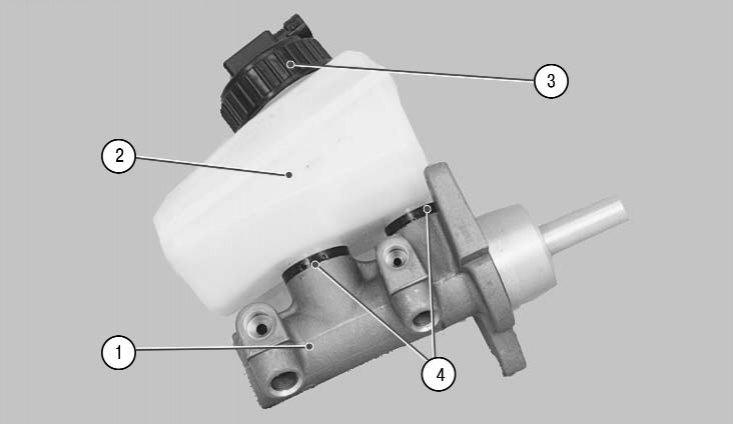
9.2. Master brake cylinder with reservoir: 1 - the main brake cylinder; 2 – a tank of the main brake cylinder; 3 - tank cap; 4 - connecting sleeves
Tank 2 is installed on the main cylinder through rubber connecting bushings 4, the internal cavity of which is divided by a partition into two compartments. Each compartment feeds one of the master cylinder chambers.
When you press the brake pedal, the pistons of the master cylinder begin to move, the working edges of the cuffs block the compensation holes, the chambers and the reservoir are separated and the brake fluid is displaced.
A brake fluid level sensor is installed in the plug 3 of the tank. If the fluid level falls below the permissible level, the warning lamp for a malfunctioning brake system lights up in the instrument cluster.
vacuum booster (pic. 9.3), installed between the pedal mechanism and the main brake cylinder, when braking due to rarefaction in the engine intake pipe through the rod and piston of the first chamber of the main cylinder, it creates an additional force proportional to the force from the pedal.
A non-return valve is installed in the hose connecting the vacuum booster to the intake pipe. It holds the vacuum in the booster as it drops down the intake pipe and prevents the air-fuel mixture from entering the vacuum booster.
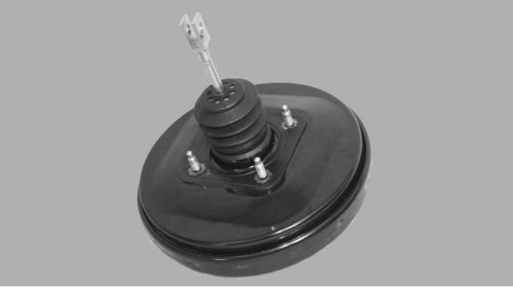
9.3. vacuum booster
The pressure regulator changes the pressure in the hydraulic drive of the rear wheel brakes depending on the load on the rear axle of the vehicle. It is included in both circuits of the brake system, through it the brake fluid flows to both rear brake mechanisms. The regulator is bolted to the car body. Its stem through a spring-loaded load rod, lever 3 (pic. 9.4) and earring 5 is connected to the rear suspension beam. Depending on the distance between the beam and the body, which is determined by the vehicle load, the regulator stem moves, which, in turn, using a valve system, changes the cross-sections of the passage channels of the circuits inside the regulator, thereby limiting the pressure in the rear brake circuits. The degree of limitation of the regulator, and consequently, the pressure in the circuits is regulated by changing the length of the regulator rod using nut 4.
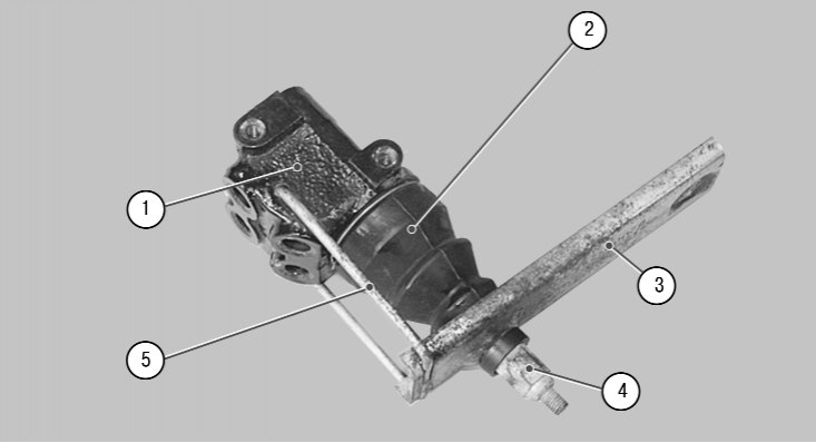
9.4. Rear brake hydraulic pressure regulator: 1 - pressure regulator housing; 2 - cover of the regulator rod; 3 - lever; 4 - adjusting nut; 5 - earring
The brake mechanism of the rear wheels is drum with automatic adjustment of the gap between the shoes and the drum. Brake pads 1 and 11 (pic. 9.5) are driven by one hydraulic working cylinder 8 with two pistons. The optimal clearance between the drum and the shoes is maintained by a mechanical regulator 6 installed on the spacer bar 9.
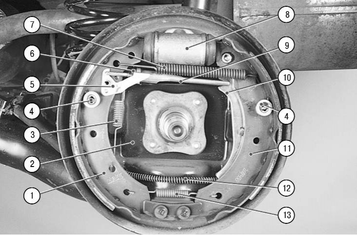
9.5. Rear wheel brake: 1 - front brake shoe; 2 - shield of the brake mechanism; 3 – a spring of the lever of a regulator of backlashes; 4 - support posts; 5 - clearance adjuster lever; 6 - clearance regulator; 7 - upper coupling spring; 8 - working cylinder; 9 - spacer bar; 10 – expanding lever of the parking brake drive; 11 - rear brake shoe; 12 - parking brake cable; 13 - lower coupling spring
The mechanically actuated parking brake consists of a lever mounted on the base of the body between the front seats, a front cable with an adjusting device and an equalizer, to which two rear cables are attached, and expanding levers installed in the rear wheel brakes.
The parking brake does not require special care. During current repairs, check the degree of wear of the teeth of the sector and pawls. Replace excessively worn parts.
If a break in the shells or wires of the cables is detected, they must be replaced with new ones.
Anti-Lock Braking System (ABS) consists of an electronic control unit (ECU), wheel speed sensors, hydraulic block 1 (pic. 9.6) with hydraulic solenoid valves, electrically driven return pump and indicator light 4 in the instrument cluster.
ABS is used to regulate the pressure in the brake mechanisms of all wheels when braking in difficult road conditions, preventing the wheels from locking. The system provides the following benefits:
- avoiding obstacles with a higher degree of safety, including during emergency braking;
- reduction of the braking distance during emergency braking while maintaining roadholding and controllability of the car, including when cornering.
In the event of a system failure, a function to maintain operation in case of system failures is provided.
Electronic control unit (ECU) receives information about vehicle speed, direction of travel and road conditions from wheel speed sensors.
Based on this information, the control unit determines the optimal wheel braking mode, changing the flow sections of the circuits using the electromagnetic valves of the hydraulic unit, anticipating the moment of blocking the wheel that slows down rotation, which prevents it from blocking.
If the system expects a wheel to lock up, it instructs the appropriate valve to isolate the fluid supply to that wheel's slave cylinder from the brake master cylinder.
If the wheel speed continues to decrease relative to the other wheels, the ABS system returns the brake fluid back to the master cylinder, reducing braking. If all four wheels decelerate equally, the return pump will shut off and all solenoid valves will open again, allowing the brake master cylinder to act on the slave cylinders normally. This cycle can repeat up to ten times per second.
Turning on the solenoid valves and the return pump creates pulsations in the hydraulic drive of the brake system, they are transmitted to the brake pedal, thereby signaling to the driver that the ABS is working.
Solenoid valves in the circuits of the brake mechanisms of the front wheels act on their working cylinders independently, on each separately, while the solenoid valve of the circuits of the brake mechanisms of the rear wheels acts on both working cylinders of the mechanisms simultaneously. Because the braking system is diagonally split, a separate mechanical plunger valve in the hydraulic block separates the rear solenoid valve's hydraulic output into two separate circuits. In order to prevent the system from being influenced by false signals, the built-in safety loop monitors all signals entering the ECU. If a false signal is received or the voltage in the on-board electrical network is insufficient, the system is automatically switched off and the ABS deactivation warning lamp in the instrument cluster lights up. In this case, the normal mode of operation of the brake system is maintained, however, when driving on a slippery road, you need to be extremely careful, since the distribution function of the system is disturbed (pressure equalization function in the brake mechanisms of the front and rear wheels) and there is a possibility of skidding the car when braking.
If there is a malfunction in the ABS system, contact a service station, as special equipment is required to diagnose and repair it.
The hydraulic brake system is integrated into a single unit with metal tubes and hoses. The system is filled with a special brake fluid of at least DOT-4 class, which must be replaced periodically. The procedure for replacing the brake fluid is described in Sec. «Maintenance» (see «Brake Fluid Replacement»).
Checking the brake system is described in sec. «Maintenance», cm. «First maintenance (TO-1)».
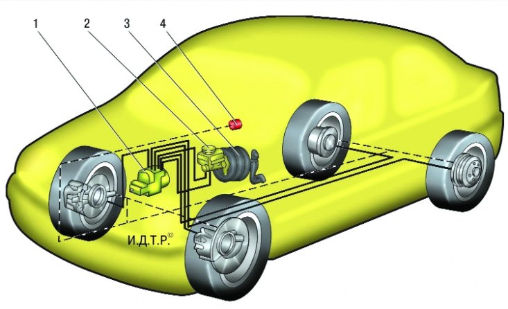
9.6. Scheme of the anti-lock braking system: 1 – hydraulic block; 2 – the main brake cylinder; 3 - vacuum brake booster; 4 – a signal lamp of shutdown of ABS in a combination of devices
Note. The working stroke of the brake pedal with the engine running should be approximately 60–65 mm. A too small stroke indicates an incorrect initial installation of the brake pedal, a violation of the adjustment of the vacuum brake booster or seizure of the working cylinder, causes increased fuel consumption and accelerated wear of the brake pads. Too large a stroke is a sign of excessive clearances in the pedal mechanism or a violation of the tightness of the hydraulic drive of the brake system. If the stroke decreases when the pedal is pressed repeatedly, i.e. she becomes «tougher», air in the system. If the full pedal travel starts to increase, the system is leaking.
If the brake pedal always starts to vibrate when braking, most likely the brake discs are warped. Unfortunately, in such a situation, they only need to be changed, and both at once. Periodically appearing and disappearing vibration of the pedal during hard braking accompanies the operation of the anti-lock brake system and is not a sign of a malfunction.
If the car starts to pull to the side when braking, check the working cylinders: they may need to be replaced.
If there is a knock in the front suspension that disappears when braking, check the tightness of the caliper mounting bolts.
After replacing the brake pads, before driving, be sure to press the brake pedal several times - the pistons in the working cylinders should fall into place.