

Pic. 3.106. Installation of bearing cages (large diameter)
Push out the bearing cages with a bushing inserted inside the crankcase (pic. 3.106).
Installation
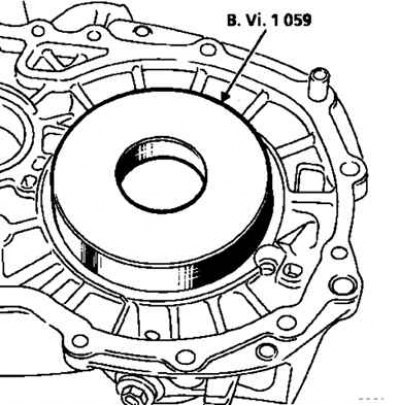
Pic. 3.106. Installation of bearing cages (large diameter)
With the aid of a device (V.Vi.1059) and press, install the bearing cages against the stop in the crankcase collars (pic. 3.106 and 3.107).
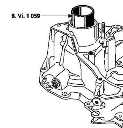
Pic. 3.107. Installation of bearing cages (small diameter)
Insert the differential housing into the crankcase, lightly oiling the bearings.
Install the planetary side bearing, preload adjustment ring and nut.
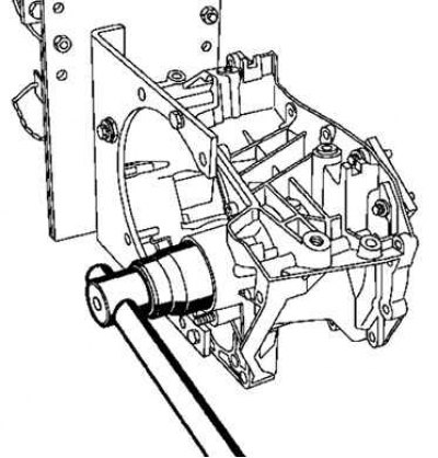
Pic. 3.108. Assembly fixing «differential housing - driven gear» using a device
As when removing, fix the assembly «differential housing-driven gear» using a device (V.Vi.1057) (pic. 3.108).
Pre-tighten to 10–20 Nm.
Remove fixture (V.Vi.1057) and rotate the differential housing to seat the bearings.
Install fixture (V.Vi.1057) and tighten the solder with a torque of 130 Nm.
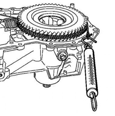
Pic. 3.109. Turning the differential case
Remove fixture (V.Vi.1057) and rotate the differential case (pic. 3.109).
Check pretension.
The differential must rotate when the following loads are applied:
- 5–20 Nm for reusable bearings;
- 16–32 Nm for new bearings.
If the adjustment does not correspond to these values, determine the thickness of the adjusting ring. At the same time, taking into account that the preload increases by about 7–8 N·m with a decrease in the thickness of the adjusting ring by 0.05 mm, and vice versa.