
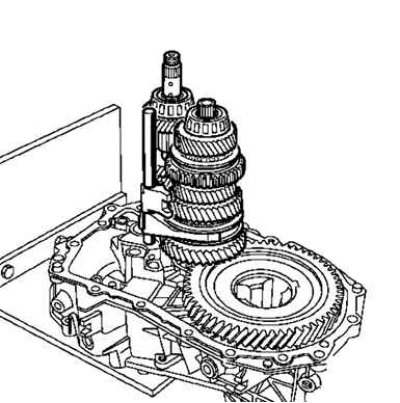
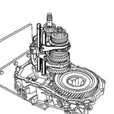
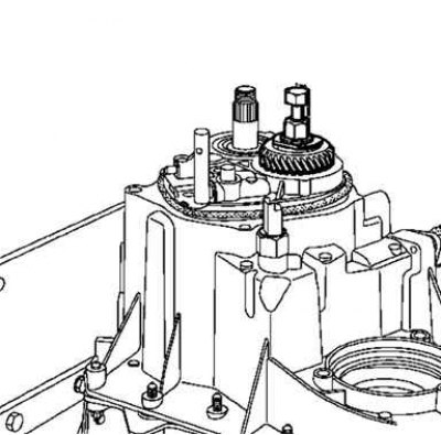
Pic. 3.112. Installing input shaft and output shaft with 1/2 yoke
Install input shaft and output shaft at the same time with 1/2 yoke (pic. 3.112).
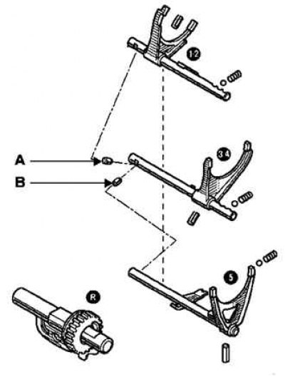
Pic. 3.113. 1/2 stem lock pin A and fifth gear stem lock pin B
Install the 1/2 stem lock pin A and the fifth gear stem lock pin B (pic. 3.113).
Raise the 3/4 hub slightly and install the yoke and 3/4 stem.
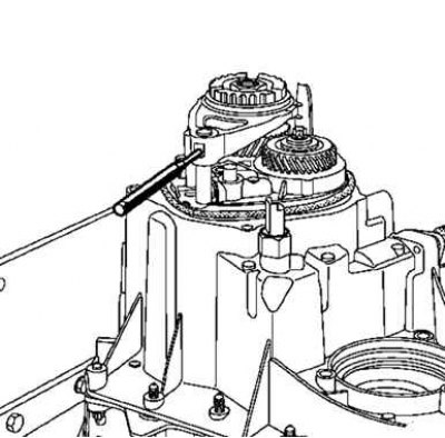
Pic. 3.114. Installing the pins in the yoke using a tool
Insert the pins into the fork using the tool (B.Vi.949) (pic. 3.114).
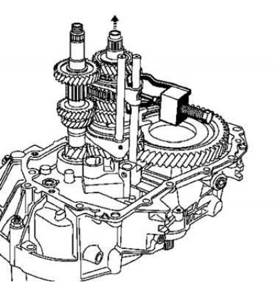
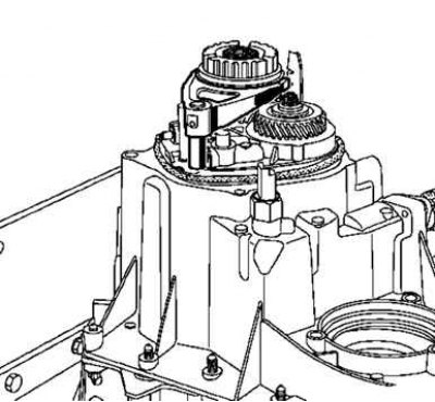
Pic. 3.115. Installing the fifth gear shaft A and the reverse axis B
Install fifth gear shaft A and reverse shaft B. To do this, slightly raise the input shaft (pic. 3.115).
Make sure the following are correctly positioned:
- centering bushings;
- magnet;
- shims for bearing preload on JR gearbox (pic. 3.116).
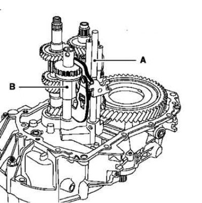
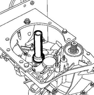
Pic. 3.116. The location of the centering sleeves, the magnet of the adjusting rings for pre-tensioning the bearings on the JR gearbox
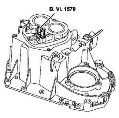
Pic. 3.117. Installation of springs and balls for blocking 1/2 and 3/4 in the crankcase
Install the 1/2 and 3/4 lock springs and balls into the crankcase and compress them with the tool (B.Vi.1570) (pic. 3.117).
Apply Loctite 518 to the joint surface.
Set third gear.
Position the crankcase with the control shaft in third gear and install the spring and ball to lock until the fifth gear stem appears.
Pic. 3.118. Squeeze ball to lock
Squeeze ball to lock and complete crankcase installation (pic. 3.118).
Remove fixture (B.Vi.1570).
Rotate the input shaft to properly install the bearings and tighten the pinch bolt to torque (25 Nm).
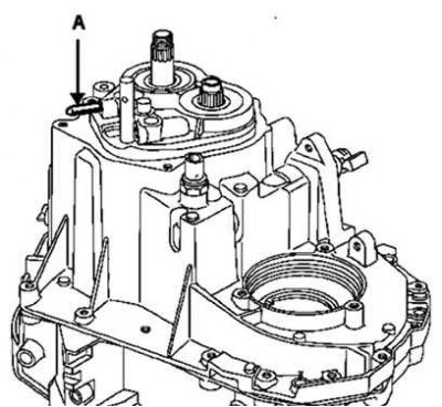
Pic. 3.119. Installing reverse axle A
Install reverse axle A (pic. 3.119).
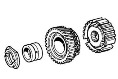
Pic. 3.120. Installing the constant mesh gear on the output shaft
Apply three drops of Loctite Frenbloc to the splines of the constant mesh gear and install with the tool (B.Vi.1175) (pic. 3.120).
Install on the input shaft:
- support ring (larger side to the gear);
- bushing under the gear;
- a fifth gear parasitic gear provided with a synchronizing ring;
- fifth gear hub with spring (pic. 3.121).
Pic. 3.121. Assembly of input shaft parts
Pic. 3.122. Installing the 5th gear fork pin
With the help of a core (B.Vi.31-01) install the fifth gear fork pin (pic. 3.122).
Pic. 3.123. Disabling first and fifth gears
Engage first gear with the shift lever, and fifth gear by sliding its fork along the stem (pic. 3.123).
Tighten the gear bolt and nut to:
- input shaft nut - 25 Nm;
- output shaft bolt - 160 Nm.
Set the transmission to neutral.
Install a new sealing ring.
Pic. 3.124. Installing the rear cover of the gearbox
Install the rear cover and tighten the bolts to 25 Nm (pic. 3.124).
Reinstall the reverse contactor.
Reinstall the speed sensor for the JH semi-automatic transmission.
Pic. 3.125. Installing the clutch shaft seal
Install the clutch shaft seal using the tool (B.Vi.1601) - for JR gearbox (pic. 3.125).

Pic. 3.126. Installing the clutch release slave cylinder
Install the clutch release slave cylinder and tighten the bolts to 21 Nm (pic. 3.126).
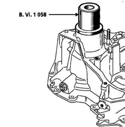
Install the differential output shaft seal using the tool (V.Vi.945) for JH gearbox and accessories (V.Vi.1058) - for JR gearbox.
JH gearbox
Place the oil-lubricated guard A on the planetary gear and fit the oil-lubricated collar C using tool B (pic. 3.127 and 3.128).
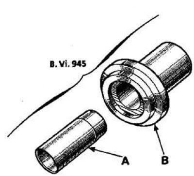
Pic. 3.127. Installing the safety sleeve A in the special tool
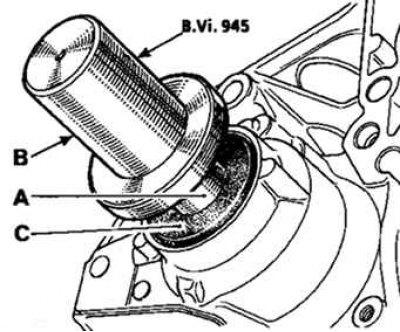
Pic. 3.128. Installation of the cuff using a special tool on the planetary gear
JR gearbox
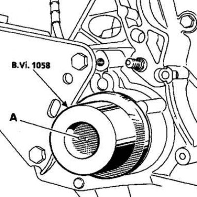
Pic. 3.129. Installing the safety sleeve A in the special tool
Place safety sleeve A in tool (V.Vi.945) on the planetary gear and put on the oiled seal using the tool (V.Vi.1058) (pic. 3.129 and 3.130).
Pic. 3.130. Installation of the cuff using a special tool on the planetary gear