
Note. Adjust only when bearings are replaced.
Install input shaft with bearings and pre-adjustment ring (V.Vi.1161) 0.62 mm thick (small outside diameter).
Install differential housing, install and tighten box connector bolts and indicator bracket plate (V.Vi.1161) on the tripod body mounts.
Install:
- sleeve (B.Vi.1527) A;
- support ring B;
- gear ring C;
- nut fully screwed in D (pic. 3.91).
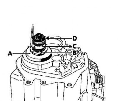
Pic. 3.91. Installation of adjusting sleeves, rings and nuts
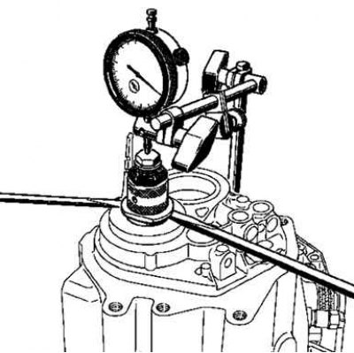
Pic. 3.92. Installing a Dial Indicator
Install a pointer type indicator with a magnetic base (pic. 3.92).
Rotate the input shaft a few times to make sure the bearings are in place.
Set zero on the indicator scale.
Using two screwdrivers as levers, pull up the input shaft.
Read the pointer type indicator.
Repeat these operations several times in the same sequence.
Determine the average value of the obtained values.
Calculate the thickness for the preload adjustment ring using the following calculation formula: thickness of the preload adjustment ring + average of the dial gauge reading - 0.02 (this value must be subtracted to ensure the minimum clearance) = thickness of the ring to be adjusted.
Example (values in mm): Thickness of pre-adjustment ring 0.62 + average of pointer gauge 0.50 - 0.02 (this value must be subtracted to ensure the minimum clearance) = thickness of the adjustment ring 1.10.
Note. A set of shims 0.86-1.30mm thick in 0.04mm increments is a replacement.