
Note. Adjust only when bearings are replaced
Install output shaft into clutch housing with bearings and pre-adjustment ring (V.Vi.1161) or similar ring 1.60 mm thick (large outside diameter).
Install crankcase.
Wrap and tighten bolts of a socket of a box.
Install the dial indicator bracket plate (V.Vi.1161) (or similar) on the tripod body mounts.
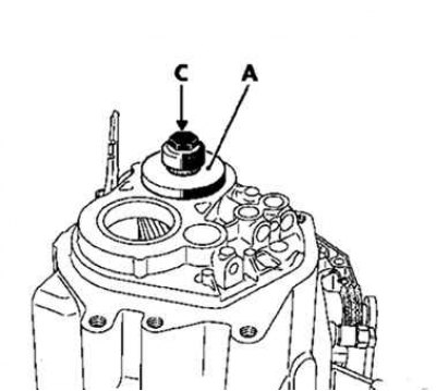
Pic. 3.89. Installation of adjusting sleeves and bolts
Install special bushing (B.Vi.1527) A and bolt C (pic. 3.89).
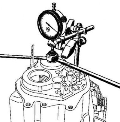
Pic. 3.90. Installing a Dial Indicator
Install a pointer type indicator with a magnetic base (pic. 3.90).
Rotate the output shaft a few times to make sure the bearings are in place.
Set zero on the indicator scale.
Using two screwdrivers as levers, pull up the output shaft.
Read the pointer type indicator.
Repeat these operations several times in the same sequence.
Determine the average value of the obtained values.
Calculate the thickness of the preload ring using the following calculation formula: prescribed value + thickness of the preload ring + average of the needle gauge = thickness of the preload ring.
Example (values in mm): prescribed value 0.26 + thickness of pre-adjustment ring 0.49 + average value of pointer indicator 1.60 = 2.35.
Note. A set of shims 2.15-2.43mm thick in 0.04mm increments is a replacement.