
Removing
1. Disconnect the ground cable from the battery.
Attention! If the car radio in your car is coded, make sure you know the code before disconnecting the battery.
Models with E7J engine
1. The high voltage ignition coil is bolted to the front of the booster box, which is mounted on the right side of the engine bay bulkhead. Please note that Renault does not supply the ignition coil separately from the booster module, but it is available from other sources.
2. Disconnect the high voltage wire from the ignition coil, then disconnect the wiring from the booster module. Loosen the ignition coil mounting bolts and carefully remove the ignition coil from the booster module.
Models with K7M engine
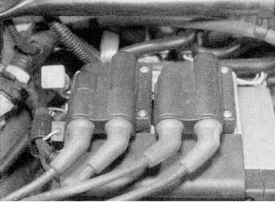
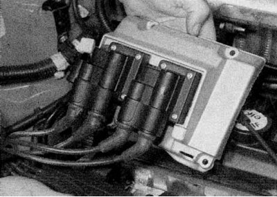
4a. The ignition coils are mounted on the right end of the valve cover (refer to accompanying illustration).
4b. Remove the ignition coil.
5. Loosen and remove the plastic cover from the front of the ignition coil assembly. Disengage the spark plug high voltage wiring from the retainer, then remove the screws securing the retainer to the ignition coil assembly and move the retainer out of the way.
6a. Loosen the screws.
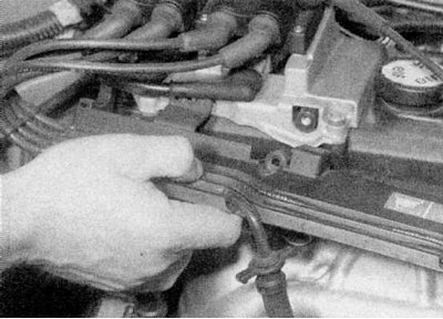
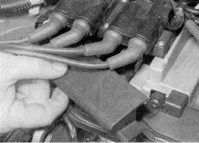
6b. Disconnect the high voltage wiring from the spark plugs.
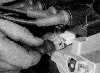
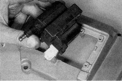
7. Disconnect the multi-pin plug from the ignition coils (refer to accompanying illustration).
8. Release the electrical wiring from the holder on the right end of the assembly.
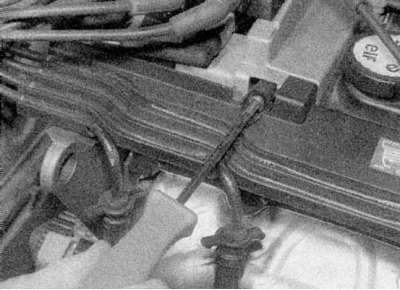
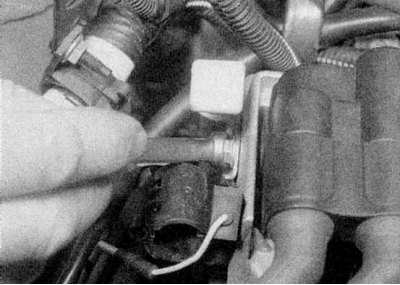
9. Disconnect a separate capacitor wire (refer to accompanying illustration).
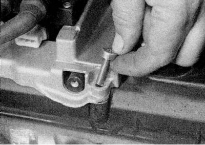
10. Remove the mounting bolt of the dipstick for measuring the level of impellent oil (refer to accompanying illustration).
11a. Loosen the four fixing screws.
11b. Remove the ignition coil assembly along with the BB wires from the valve cover. Note that the screws are mounted on top of the valve cover screws (refer to illustrations).
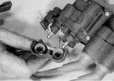
12. Carefully disconnect the spark plug high voltage wiring from the ignition coils (refer to illustrations).
Note. The bases of the ignition coils are different to ensure that they can only be installed in one position.
Models with F3R engine
1. The ignition coils are mounted on the front side of the engine.
2. Disconnect the high voltage wiring from the spark plugs.
3. Disconnect the multi-pin plug from the ignition coils and a separate wire from the capacitor.
 |  |
4. Remove the four screws securing each ignition coil to the mounting bracket and remove the ignition coils along with the spark plug BB wires.
Note. The bases of the ignition coils are different to ensure that they can only be installed in one position.
5. Carefully disconnect the high voltage wiring from the ignition coils.
Models with F7R engine
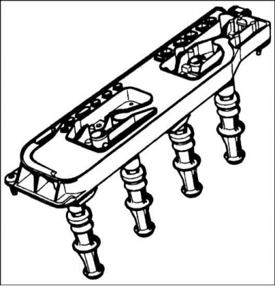
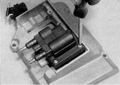
1. The ignition coils are integrated into an assembly mounted in the center of the valve cover. Ignition coils are mounted directly on the spark plugs and high voltage wires are not required. The ignition coils cannot be separated from the assembly and if any coil fails, the entire assembly must be replaced (refer to accompanying illustration).
2. Where available, remove the front suspension tie rod above the engine.
3. Loosen the two screws and remove the plastic cover from the top of the ignition coil assembly.
4. Disconnect the multi-pin wiring plug at the end of the assembly.
5. Turn away seven fixing screws and remove ignition coils from spark plugs.
Examination
Models with E7J engine
1. Checking the health of the ignition coil comes down to the continuity of its windings (between clamps "+" And "-" primary, and between the LT+ and HT terminals of the secondary). Compare your results with those given in Specifications at the beginning of this chapter. Note that the resistance of the ignition coil windings may vary slightly with coil temperature, results in Specifications - approximate, since no exact data is given by Renault.
2. Check that there is no electrical conductivity between the high voltage wire terminal and the ignition coil housing.
3. If the ignition coil is defective, replace it.
Models with K7M and F3R engine
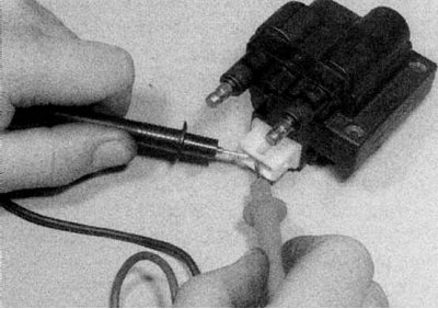
1a. Each ignition coil can be tested with a multimeter in resistance measurement mode. Connect the multimeter to the terminals and compare the measured results with the information provided in Specifications. The three terminals of the low voltage circuit are marked with numbers on the socket.
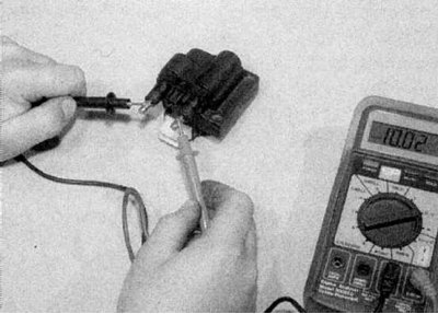
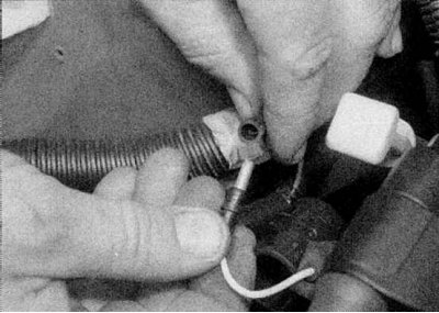
1b. At the end of the test, connect a multimeter between two HV terminals (refer to illustrations).
2. Replace the ignition coil if it is defective, but remember that they are different.
Models with F7R engine
1. Each ignition coil can be tested with a multimeter in resistance measurement mode. Connect the multimeter to the terminals and compare the measured results with the information provided in Specifications. The four low voltage terminals are numbered from 1 to 4, terminal #1 is the one closest to the bulkhead of the engine compartment. Connect a multimeter between the BB terminals for cylinders #1 and #4, and then for cylinders #2 and #3.
2. Replace the ignition coil assembly if any of the coils is defective.
Installation
1. Install in reverse order, making sure that the wiring connectors are correctly and securely fastened.