



Note: New steering gear nuts and bolts will be required for installation.
Block the rear wheels, set the handbrake, then jack up the front of the car and place it on axle stands. Remove the front wheels.
Removal
Steering gear without power assistance
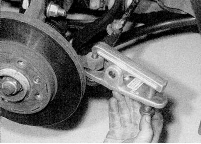
1. Remove the nuts securing the ball joints of the tie rods to the steering knuckles. Release the ball joint rods using a special puller (refer to the accompanying illustration).
2. While working under the vehicle, release the mounting bracket (where is available) and peel back the protective rubber boot to gain access to the lower universal joint of the steering column shaft. Use paint or a marker to mark the universal joint and the steering gear pinion. Loosen and remove the nut and bolt of the clamp that secures the joint to the pinion.
3. Remove the two nuts securing the steering gear assembly to the subframe. Separate the steering gear pinion from the universal joint and remove the assembly from under the vehicle. Remove the rubber boot. Discard the mounting nuts and bolts - they are subject to replacement.
Power steering
1. Remove the exhaust pipe/converter as described in Chapter Power and exhaust systems. If necessary, remove the air cleaner cover to gain easier access to the steering gear assembly.
2. Follow the steps described in paragraphs 2 and 3 above.
Warning: On vehicles equipped with an airbag, before removing the column shaft, place the wheels in the straight ahead position and lock the steering wheel with a suitable tool. Failure to do so will damage the airbag wiring terminal block.
3. Using special clamps, pinch the feed and return hoses of the mechanism near the reservoir of the hydraulic system of the booster. This will reduce the loss of fluid during the subsequent steps.
4. Mark the hoses relative to the couplings to avoid confusion during installation. Unscrew the tube coupling nuts on the steering gear assembly. Be prepared for fluid to escape and place a suitable container under the ends of the tubes. Separate both tubes and plug their ends and the openings in the steering gear to prevent further fluid loss. Remove the O-rings from the coupling nuts and discard them - they must be replaced.
5. Remove the nuts/bolts securing the feed and return pipes to the subframe and move the pipes away from the steering gear.
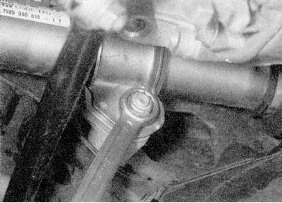
6. Remove the steering gear mounting bolts and nuts, then remove the mounting clamp halves and rubber bushings (refer to the accompanying illustration). Discard the mounting nuts and bolts - they must be replaced.
7. On Scenic models, remove the bolt securing the lower control arm brace to the left front fender side member and the nut securing it to the control arm itself. Remove the brace from the vehicle.
8. Separate the steering gear pinion from the universal joint, then slide the gear assembly out from under the vehicle. Note that on Scenic models, you may need to have an assistant move the engine/transmission as far forward as possible.
Inspection
1. Inspect the steering gear assembly for damage or wear, and ensure that the rack moves freely through its full travel without excessive play between the pinion and rack. On models with power steering, inspect all steering gear couplings for leaks and ensure that their nuts are tight.
2. The steering gear cannot be overhauled. The only replaceable components are the protective covers, the ball joints of the steering rods and the rods themselves.
Installation
Steering gear without power assistance
1. Install the steering gear and rubber boot in the working position. Install the universal joint on the grooves of the steering gear pinion, aligning the marks made before removal.
2. Insert new mounting bolts, then install the nuts and tighten them to the specified Specifications effort.
3. Install the universal joint tie bolt and nut and tighten to the specified torque. Move the protective cover into the working position and attach it with a new tie.
4. Install the steering rod ball joints into the steering knuckles and tighten their mounting nuts to the specified tightening torque.
5. Install the wheels, lower the vehicle to the ground and tighten the wheel bolts to the specified Specifications effort.
6. Finally, check and, if necessary, adjust the front wheel alignment as described in Section Wheel alignment angles.
Power steering
1. Bring the steering gear assembly and rubber boot into working position. Install the universal joint onto the steering gear pinion grooves, aligning the marks made prior to removal.
2. Install the rubber bushings on the mechanism and place the halves of the mounting clamps in the working position. Install the new mounting bolts and nuts and tighten them by hand for now.
3. Install new O-rings onto the steering gear coupling nuts and connect the tubes to the mechanism. Screw each coupling nut in a few turns, then install the tube bracket nuts/bolts, but do not tighten them yet.
(This note was copied from the resource www.RENAULTBOOK.ru)
4. Tighten the steering gear mounting bolts and nuts to the specified Specifications force, then tighten the tube connecting nuts. After that, tighten the tube mounting bracket nuts/bolts securely.
5. Install the universal joint pinch bolt and tighten its nut to the specified torque Specifications force. Move the protective cover to the working position.
6. Insert the ball joints of the steering rods into the steering knuckles and tighten their mounting nuts to the specified Specifications effort.
7. Where available, install the lower control arm brace.
8. Install the exhaust/converter downpipe and (where removed) air filter housing as described in Chapter Power and exhaust systems.
9. Install the wheels, lower the vehicle to the ground and tighten the wheel bolts to the specified Specifications effort.
10. Remove the clamps from the hoses and bleed the power steering system as described in Section Bleeding the hydraulic system of the power steering.
11. Finally, check and, if necessary, adjust the front wheel alignment as described in Section Wheel alignment angles.