
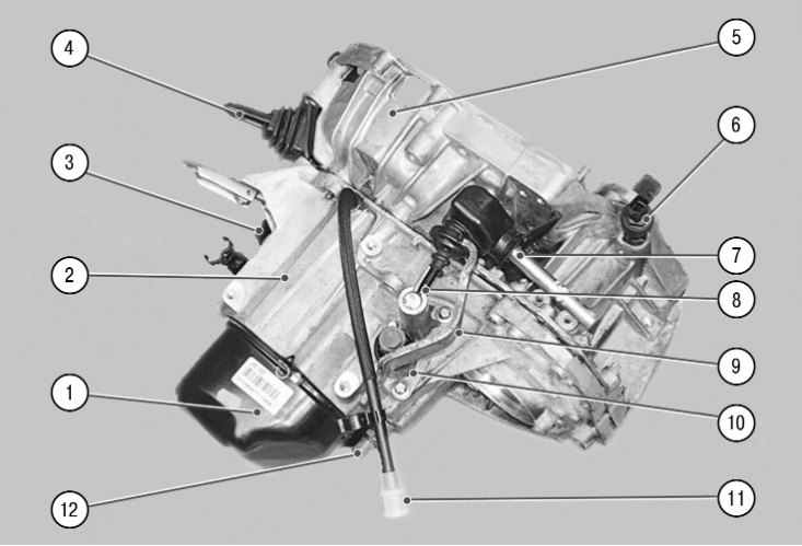
6.3. Transmission: 1 - back cover; 2 - gearbox housing; 3 - filler plug; 4 - clutch release fork; 5 - clutch housing; 6 – speed sensor; 7 - gearbox control lever; 8 – a stock of a choice of transfers; 9 - gear lever; 10 - gear shift mechanism; 11 - breather; 12 - reverse light switch
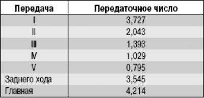
Renault Logan cars are equipped with a five-speed manual gearbox (pic. 6.3). With K7J engine (working volume 1.4 l) mount gearbox JH1, with engine K7M (working volume 1.6 l) – JH3. Both gearboxes are almost identical in design and differ only in the size of the clutch housings. gear ratios (tab. 6.1) both gearboxes are the same.
Table 6.1 Gearbox ratios
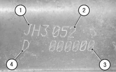
6.4. Gearbox identification data: 1 - type of gearbox; 2 - modification of the gearbox; 3 - serial number of the gearbox; 4 - manufacturer's code
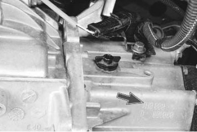
The gearbox identification data is stamped on the bottom of its crankcase. The decoding of the identification data is shown in fig. 6.4.
The gearbox is made according to a two-shaft scheme with five synchronized forward gears. The gearbox and final drive with differential share a common crankcase. The clutch housing is attached to the front of the gearbox housing. A stamped steel cover is installed on the rear of the gearbox housing.
On the input shaft there is a V gear rotating on a needle bearing with a synchronizer, and the drive gears of I, II, III and IV gears are made in one piece with the input shaft.
The secondary shaft is made together with the drive gear of the main gear, in addition, freely rotating driven gears of I, II, III and IV gears and a driven gear of the V gear fixed on the splines of the shaft are installed on the shaft.
The forward gears are switched on by axial movement of the clutches of two synchronizers of I–II and III–IV gears mounted on the output shaft, and the synchronizer clutch of the 5th gear mounted on the input shaft. Shift mechanism 10 (see fig. 6.3) is located in the cover mounted on top of the crankcase 2 of the gearbox.
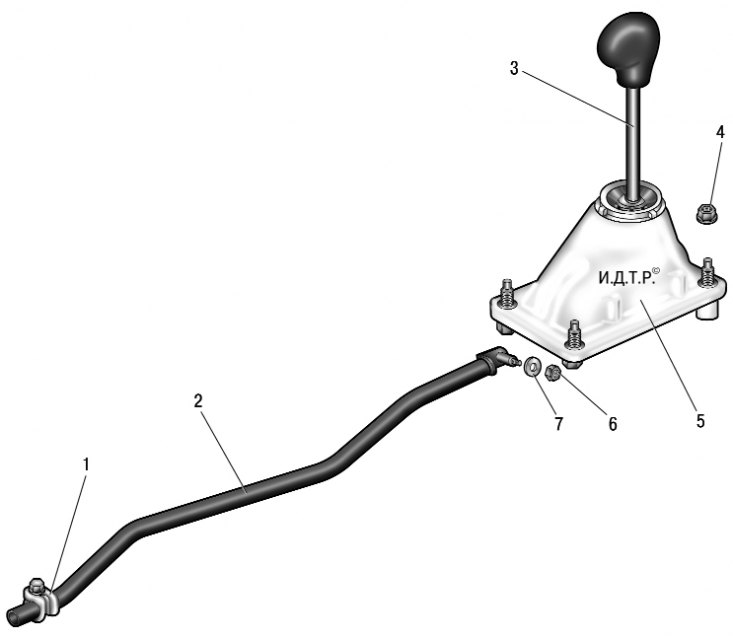
6.5. Gearbox control drive: 1 – a collar of fastening of draft of a drive of management of a transmission; 2 – draft of a drive of management of a transmission; 3 – gear control lever; 4, 6 - nuts; 5 – a scene of the lever of management of a transmission; 7 - washer
The gearbox control drive consists of a backstage 5 (pic. 6.5) gearshift lever 3 with a ball joint fixed to the base of the body with nuts 4, rods 2 of the gearbox control drive and mechanism 10 (see fig. 6.3), installed on the gearbox housing.
The main gear is made in the form of a pair of cylindrical gears matched according to noise. Torque is transmitted from the driven gear of the final drive to the differential and then to the front wheel drives.
The differential is conical, two-satellite. The tightness of the connection of the inner hinge of the right drive of the front wheel with the differential gear is ensured by an oil seal pressed into the gearbox housing, and the inner hinge of the left drive is provided by an oil seal installed in the hinge cover. The cover of the internal hinge of the left drive is fixedly fixed by a special holder on the gearbox housing, and the drive shaft rotates inside the cover on a ball bearing.
In the lower part of the gearbox housing there is a drain plug, and on the side there is a filler plug 3.
To repair a gearbox, a large set of special tools and appropriate training of the performer are required, therefore, this section discusses only the removal and installation of the gearbox, replacing its seals and repairing the drive. If it is necessary to repair the gearbox, contact a specialized service.
The procedure for changing the oil in the gearbox is described in Sec. 4 «Maintenance» (see «Checking the level and adding oil to the gearbox»).