
Attention! If a new torque converter or transmission is to be installed, reprogram the ECU using the XR25 tester.
Special tool:
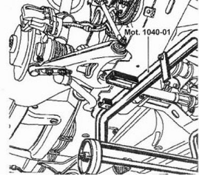
- Subframe support - Mot. 1040-01
- Ball joint puller - T.Av. 476
- Brake caliper bolts - 40 Nm
- Lower ball joint nut - 55 Nm
- Shock absorber support bolt - 180 Nm
- Engine tie rod bolt - 65 Nm
- Starter bolt - 45 Nm
- Gearbox support bolt - 40 Nm
- Wheel bolt - 90 Nm
- Tie rod ball joint nut - 40 Nm
- Torque converter clutch nut - 30 Nm
- Heat exchanger support bolt - 50 Nm
- Modular jack support bolt - 20 Nm
Do not remove the transmission from the vehicle for an intended repair until a professional diagnosis has been made as many checks can only be performed with the transmission installed in the vehicle.
Removing
1. Put the car on a lift.
2. Remove the battery.
3. Remove the front wheels.
4. Remove the air filter duct.
5. Remove the battery tray.
6. Remove the bolt (2) fastening of the hinge of a cable of the combined switch.
7. Release the cable (1) switch from the central switch holder.
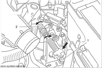
Figure 4.38. Disconnecting the ball end (2) selector cable and turning locking rings (1) cable sheaths in different directions (the arrow shows the movable part of the hydraulic distributor)
Note. Do not move the orange ring during this operation. It may break during removal or installation. If this happens, do not replace the selector cable, as the absence of the ring does not affect the operation of the system.
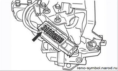
Figure 4.39. Modular gearbox connector (arrow)
8. Disconnect the modular connector (Figure 4.39), freeing his wiring.
Attention! After disconnecting the connector, place a moisture-proof bag over the connector.
9. Turn away bolts of fastening of the supporting arms of conducting of the engine. Remove support bracket (1) and TDC sensor (2).
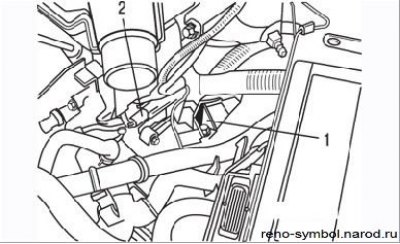
Figure 4.40. Harness mounting bracket (1) wires, sensor (2) TDC
10. Clamp the heat exchanger hoses with clamps, disconnect the hoses.
11. Disconnect the oxygen sensor connector.
12. Remove both drive shafts.
13. Remove the steering mechanism mounting bolts, fix it to the side so that it does not interfere with the removal of the automatic transmission and without damaging the mechanism hoses.
14. Disconnect the vehicle speed sensor connector.
15. Remove:
- starter;
- jet thrust of the engine;
- intake pipe of the exhaust system.
16. Fit the subframe trolley holder Mot.1040-01.
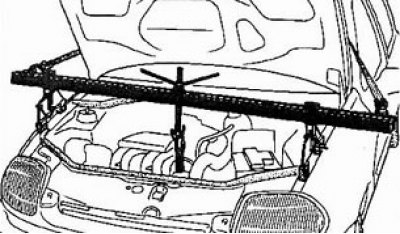
17. Establish an engine support, fix the engine on it.
18. Remove the engine subframe.
19. Rotate the crankshaft clockwise to install the three bolts securing the torque converter to the drive clutch against the access hole. Turn away bolts.
20. Remove the automatic transmission support and ground cable.
21. Tilt the power package as low as possible.
Attention! Be careful not to damage the A/C compressor.
22. Turn away bolts and the top nuts of fastening of automatic transmission to the engine.
23. Move a jack under the automatic transmission.
24. Remove the bolts and lower nuts securing the automatic transmission to the engine.
25. Carefully disconnect the automatic transmission from the engine. The torque converter must remain on the transmission shaft.
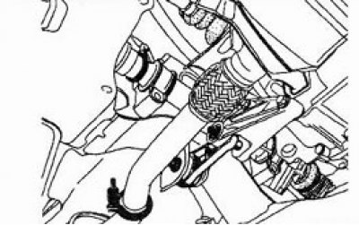
26. Secure the torque converter with twine to the automatic transmission case.
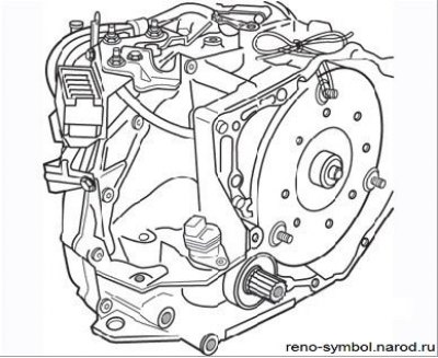
Figure 4.41. Fixing the torque converter with a cord to prevent its displacement
Installation
- untie the torque converter and align it with the gearbox. Apply a coat of Molykote BR2 moly grease to the torque converter center ring;
- install the guide bushings in their places and clean the threads of the torque converter mounting posts to the faceplate;
- when installing the gearbox, align the torque converter threaded posts with the holes in the faceplate. Apply Loctite Frenbloc anaerobic sealant to the threads of the new nuts, screw them on and tighten to the specified torque;
- connect the selector cable and adjust it as described below;
- perform the remaining operations in the reverse order of removal;
- Finally, top up the box with the correct amount of fluid of the type prescribed, as described above.