
Fuel line and injectors (models with K7M and F3R engine)
Removing
1. Disconnect the ground cable from the battery (contact the head Engine electrical equipment for Scenic models).
Attention! If the car radio in your car is coded, make sure you know the code before disconnecting the battery.
2. Unscrew the reinforcing rod, where applicable, between the domes of the front suspension struts.
3. Disconnect the crankcase ventilation hoses from the cylinder head. On models with an F3R engine, release and remove the plastic wire harness cover from the top of the intake manifold.
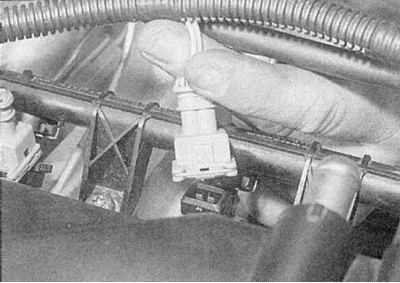
4. Disconnect the wiring from the injectors, EVAP solenoid valve, idle control stepper motor, and intake air temperature sensor. Move the wiring harness to the side (refer to accompanying illustration).
5. Disconnect the vacuum hose connecting the pressure regulator (on the fuel line) with inlet pipe.
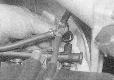
6. Disconnect the fuel supply and return hoses from the fuel line (refer to accompanying illustration).
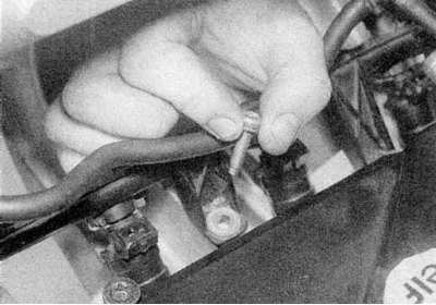
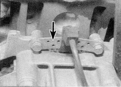
7. Unscrew and remove the fixing bolts and carefully separate the fuel line together with the injectors from the intake manifold (refer to accompanying illustration).
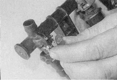
8a. Note the location of the injectors, then remove the brackets.
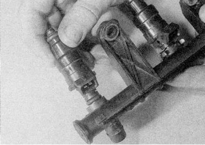
8b. Separate the injectors from the fuel line (refer to accompanying illustration).
9. Remove the O-rings from the grooves at the ends of the injectors and purchase new ones.
Installation
1. Install in reverse order, paying attention to the following:
- a) Replace all o-rings.
- b) Install the fuel line assembly on the pipeline and tighten the mounting bolts as shown in Specifications effort.
- With) Finally, start the engine and check for fuel leaks.
Fuel line and injectors (models with F7R engine)
Removing
1. Disconnect the ground cable from the battery.
Attention! If the car radio in your car is coded, make sure you know the code before disconnecting the battery.
2. Unscrew the reinforcing rod, where applicable, between the domes of the front suspension struts.
3. Remove the air filter assembly as described in Section Removal and installation - air filter assembly and intake ducts.
4. Disconnect electrical connectors from the following components:
- a) Camshaft position sensor.
- b) Pipeline pressure sensor.
- With) Coolant temperature sensor and temperature gauge sensor.
- d) Speed/crankshaft position sensor.
- e) Throttle Potentiometer.
- f) Stepper idle control motor.
- g) EGR solenoid valve.
- h) fuel injectors.
- i) BB ignition coils.
5. Disconnect the fuel supply and return hoses from the fuel line.
6. Disconnect the crankcase ventilation hoses from the cylinder head, then release from the mounts and remove the wiring harness from the top of the intake manifold, move it to the side.
7. Disconnect the vacuum hose connecting the pressure regulator (on the fuel line) with inlet pipe.
8. Disconnect the fuel supply and return hoses from the fuel line.
9. Turn away and remove fixing nuts and accurately separate a fuel highway together with atomizers from a head of the block of cylinders.
10. Note the location of the injectors, then remove the brackets and separate the injectors from the fuel line.
11. Remove the groove o-rings at the ends of the injectors and purchase new ones.
Installation
1. Install in reverse order, paying attention to the following:
- a) Replace all o-rings.
- b) Install the fuel line assembly to the cylinder head and tighten the mounting bolts as shown in Specifications effort.
- With) Finally, start the engine and check for fuel leaks.
Fuel pressure control
Removing
1. Disconnect the vacuum tube from the regulator (refer to illustrations).
2. Place a wad of cloth under the regulator, then remove the retainer spring and separate the fuel line regulator.
3. Remove the O-rings from the grooves in the pressure regulator and purchase new ones.
Installation
1. When installing, use new o-rings in the grooves of the regulator. Attach the regulator to the fuel line and install the retainer spring and vacuum tube.
Throttle Potentiometer
Removing
1. Remove the throttle body as described in Section Removal and installation of the throttle body.
2. Turn away screws of fastening and remove a potentiometer from the case of a throttle.
3. Install in reverse order, making sure the potentiometer is correctly connected to the throttle shaft.
Installation
1. Install in reverse order, making sure the potentiometer is properly connected to the throttle shaft.
Note. After each removal of the potentiometer, Renault recommends checking its function using the XR25 diagnostic tool.
Inlet air temperature sensor
Removing
1. On models with a K7M engine, remove the intake air duct as described in Section Removal and installation - air filter assembly and intake ducts.
2. Unscrew and remove the intake air temperature sensor from the intake air duct or air filter housing.
Installation
1. Install in reverse order.
Coolant temperature sensor
1. The sensor is located on the thermostat housing at the left end of the cylinder head. For details on removal and installation, see Chapter Cooling, heating system.
Power steering pressure sensor
Removing
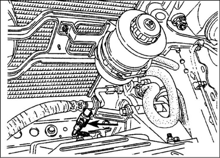
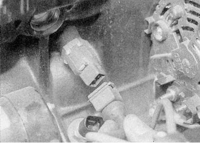
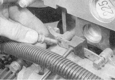
1. The sensor is screwed into the supply pipe from the power steering pump to the steering gear (refer to accompanying illustration).
2. To remove the switch, disconnect the wiring connector.
3. Wipe the area around the switch, then unscrew the switch and remove it from the pipe. Seal the hole in the pipe to prevent fluid leakage and dirt from entering the hydraulic system.
Installation
1. Installation is carried out in the reverse order. Finally, check the fluid level in the power steering hydraulic system.
Knock sensor
1. Contact the Head Engine electrical equipment.
Idling stepper motor
Removing
1. The stepper motor is mounted on top of the throttle body. To remove it, first remove the throttle body as described in Section Removal and installation of the throttle body.
2. Loosen the mounting screws and remove the stepper motor from the throttle body. Remove the gasket - it must be replaced.
Installation
1. Install in reverse order using a new gasket.
Pipe pressure sensor
Removing
1. The sensor is installed on the left side of the bulkhead of the engine compartment.
2. Disconnect the wiring from the sensor.
3. Turn away fixing nuts and remove the gauge.
Installation
1. Install in reverse order.
Fuel injection relay and priming pump relay
Removing
1. These relays are located in the fuse/relay box in the engine compartment (relay "J" And "L").
2. Remove the cover from the unit
3. Remove the appropriate relay.
Installation
1. Installation is carried out in the reverse order.
Speed/Crankshaft Position Sensor
Removing
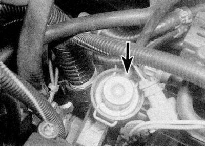
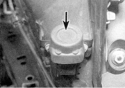
1. The sensor is mounted on top of the clutch housing (refer to accompanying illustration).
2. To remove the sensor, disconnect the earth cable from the battery (contact the head Engine electrical equipment for Scenic models), then remove the air filter cover as described in Section Removal and installation - air filter assembly and intake ducts.
3. Trace the wiring from the sensor to the connector and disconnect it from the main harness.
4. Turn away bolts of fastening and remove the gauge (refer to accompanying illustration).
Installation
1. Install in reverse order. Tighten the sensor mounting bolts securely - note that only special bolts should be used; these bolts accurately mount the transducer, providing the correct air gap between the handpiece and the flywheel/drive plate.
Camshaft position sensor
Removing
1. The sensor is installed on the left (F3R engines) or right (F7R engine) end of the cylinder head.
2. Disconnect the wiring connector, then unscrew the fastening bolt and remove the sensor from the casing.
Installation
1. Installation is carried out in the reverse order.
Inertial fuel cut switch
Removing
1. The inertial switch is located on the left side of the engine compartment.
2. Turn away and remove screws of fastening of the switch, then disconnect electroconducting and remove the switch.
Installation
1. Installation is carried out in the reverse order. Finally, reset the switch by pressing the button.
Electronic control module (ecu)
Attention! On vehicles with an anti-theft system that includes an immobilizer, the electronic control module is coded. If it is necessary to replace the control module, entrust this work to a Renault workshop. After installing a new unit, it is necessary to enter the correct code into it - this can only be done using the Renault XR25 diagnostic tool
Removing
1. The electronic control module is located in the front right corner of the engine compartment.
2. To remove the control module, first disconnect the earth cable from the battery (contact the head Engine electrical equipment for Scenic models).
Attention! If the car radio in your car is coded, make sure you know the code before disconnecting the battery.
3. Where applicable, unscrew the bracket from the top of the control box and release the strap.
4. Turn away fixing screws and remove the electronic control module.
5. Disconnect the wiring connector.
Installation
1. Install in reverse order.