English Русский
Български
Беларускі
Український
Српски
Hrvatski
Română
Polski
Slovenský
Magyar
Bookmark Contacts Articles Sitemap
Company vehicles Peugeot Company vehicles Opel Company vehicles Skoda Company vehicles Land Rover Company vehicles Mitsubishi Company vehicles Volkswagen Company vehicles Honda
RenaultBook.ru


Duster   Fluence   Kangoo   Laguna   Logan   Megane   Sandero   Scenic   Symbol   Clio   Other
Symbol 1 (1999-2008, petrol) Symbol 2 (2008-2013, petrol)

Removal and installation fuel system sensors (Renault Symbol 1)

  • Main
  • Symbol
  • Symbol 1 (1999-2008, petrol)
  • Power unit
  • Supply system
  • Removal and installation fuel system sensors
0
Contents: Removal and installation the upper…🠛 Removal and installation the knock…🠛 Removal and installation the…🠛 Removal and installation the coolant…🠛 Removal, installation and checking…🠛 Removal and installation the…🠛

Removal and installation the upper exhaust gas oxygen concentration sensor


Removal procedure:
  • disconnect the negative battery cable;
  • remove the air filter housing;

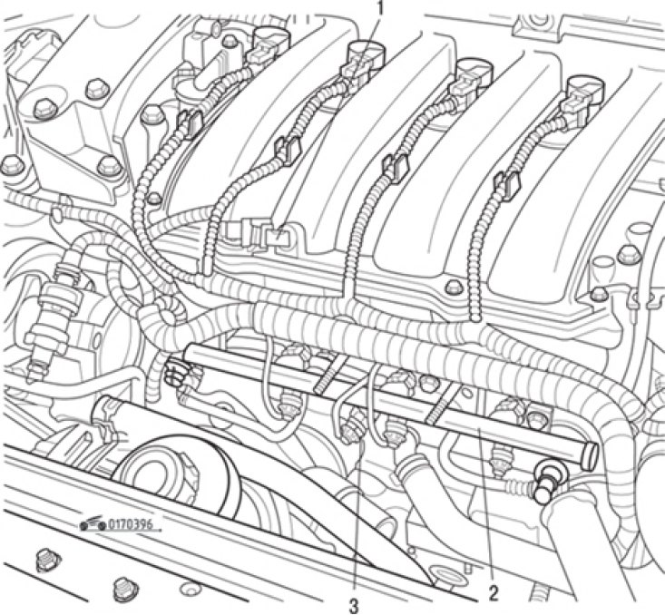
Fig. 3.96. Location on the engine of the sensor (1) for incoming air temperature, fuel rail (2),…

Fig. 3.96. Location on the engine of the sensor (1) for incoming air temperature, fuel rail (2), knock sensor (3)

  • disconnect the sensor connector and remove the sensor using tool Mot. 195 (see fig. 3.96).

The sensor is installed in the reverse order of removal.

Note: Make sure the heat shield is securely fastened between the oxygen sensor and the manifold (to avoid overheating, which may result in destruction of the sensor connector).


Removal and installation the knock sensor


The knock sensor is installed in the rear wall of the cylinder block (see fig. 3.105). The process of removing and installing the sensor is described in the subsection "Ignition system".

Removal and installation the incoming air temperature sensor


The location of the sensor on the engine is shown in Fig. 3.97.


Removing the sensor is not difficult. Disconnect the connector and unscrew the sensor. Install the sensor in the reverse order of removal.

Removal and installation the coolant temperature sensor


The sensor is installed in the thermostat housing. It is a resistor with a negative temperature coefficient of resistance, i.e. as the air temperature increases, the electrical resistance of the sensor decreases (see table 3.6). The verification and installation process is described in the subsection "Cooling system".

Removal, installation and checking the throttle potentiometer


Removal procedure:
  • remove the throttle body as described above;
  • loosen the mounting screws and remove the potentiometer from the throttle body.

Installation procedure:
  • correctly align the potentiometer with the throttle shaft;
  • screw in the potentiometer mounting bolts;
  • check the resistance between the potentiometer contacts, which should correspond to the values given in Table 3.8.

Table 3.8. Resistance between potentiometer contacts depending on the accelerator pedal position



Table 3.8. Resistance between potentiometer contacts depending on the accelerator pedal position

Removal and installation the crankshaft position sensor
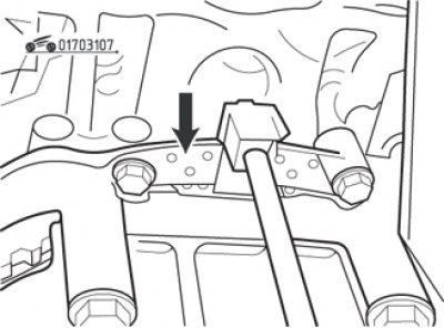


Fig. 3.107. Crankshaft position sensor (arrow)

Fig. 3.107. Crankshaft position sensor (arrow)


The crankshaft position sensor is located on top of the clutch housing on the left side of the engine cylinder block (fig. 3.107).

Removal procedure:
  • remove the air filter housing;
  • disconnect the contact connector from the sensor;
  • unscrew the mounting bolts and remove the sensor.
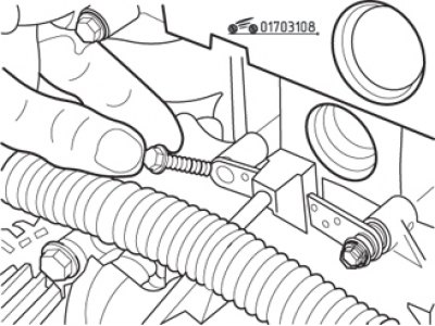
Fig. 3.108. Special bolts used to secure the crankshaft position sensor

Fig. 3.108. Special bolts used to secure the crankshaft position sensor


Installation is carried out in the reverse order of removal, while paying attention to the shaped mounting bolts (fig. 3.108), which cannot be replaced with others, as the gap between the sensor and the flywheel teeth may be damaged.
This article is available on: russian, bulgarian, belarusian, ukrainian, serbian, croatian, romanian, polish, slovak, hungarian
Article has been reviewed by editor: Podkrepilov Maxim
Share with friends:
Previous
Symbol 1: Supply system
Next

Fuel supply switch in case of collision
Removal and installation the idle speed control valve
Checking the fuel supply pressure
Checking the fuel pump supply
Removal and installation the fuel rail
Removal and installation of the electronic control unit (ECU)
Removal and installation the intake manifold
Removal and installation the exhaust manifold
Checking and adjusting the injection system
Other articles on other Renault models

➽ Functional diagram of the fuel supply system Renault Duster 1 (2009-2017)
➽ Technical characteristics of engines for diagnostic procedures… Renault Fluence 1 (2009-2020, petrol)
➽ Fuel vapor recovery system Renault Kangoo 1 (1997-2007)
➽ Description of the fuel system design Renault Laguna 2 (2001-2007)
➽ Checking the engine fuel system Renault Logan 1 (2004-2012, petrol)
Link to this article in different formats
Reviews and comments of visitors
No comments yet


Add two numbers 21 + 27


Symbol 2 (2008-2013, petrol) 
  • General information
  • User manual
  • Maintenance
  • Power unit
  • Engine repair
  • Cooling system
  • Fuel system
  • Exhaust system
  • Ignition system
  • Transmission
  • Clutch
  • Mechanical gearbox
  • Automatic gearbox
  • Drive shafts
  • Chassis, running gear
  • Front suspension
  • Rear suspension
  • Steering
  • Brake system
  • Body and interior
  • Exterior (external elements)
  • Interior (internal elements)
  • Doors, locks and windows
  • Heating and ventilation
  • Electrical equipment
  • Equipment and devices
  • Headlights and lighting
  • Power devices
  • Electrical circuits
Symbol 1 (1999-2008, petrol) 
  • General information
  • User manual
  • Car care
  • Maintenance
  • Power unit
  • Engine repair
  • Cooling and lubrication system
  • Supply system
  • Exhaust system
  • Ignition system
  • Transmission
  • Clutch
  • Mechanical gearbox
  • Automatic gearbox
  • Drive shafts
  • Chassis, running gear
  • Car suspension
  • Steering
  • Brake system
  • Body and interior
  • Exterior (external elements)
  • Interior (internal elements)
  • Doors, locks and windows
  • Restoration and repair
  • Electrical equipment
  • Equipment and devices
  • Headlights and lighting
  • Power devices
  • Heating and ventilation
  • Electrical circuits
RenaultBook.ru © 2018–2026 | Mobile version | News and articles | Sitemap: EN BG BY UA RS HR RO PL SK HU | Administration | Site search | Bookmark
Duster 1 (2009-2017) | Fluence 1 (2009-2020, petrol) | Kangoo 1 (1997-2007) | Laguna 2 (2001-2007) | Logan 1 (2004-2012, petrol) | Logan 2 (2012-2020) | Megane 1 (1995-2002) | Megan 2 (2002-2009, petrol) | Sandero 1 (2007-2012, petrol) | Scenic 1 (1996-2003) | Symbol 1 (1999-2008, petrol) | Symbol 2 (2008-2013, petrol) | Renault 19 (1988-1996) | Espace I and II (1984-1996) | Espace III (1996-2002) | Clio 1 (1990-1998) |
We want your visit to be comfortable 😌 and use cookies 🍪 to do so.