
Fuel injector
Note. If an injector malfunction is suspected, it is worth trying one of the special cleaners before throwing it away.
Removing
1. Remove the inlet air temperature sensor as described later in this Section.
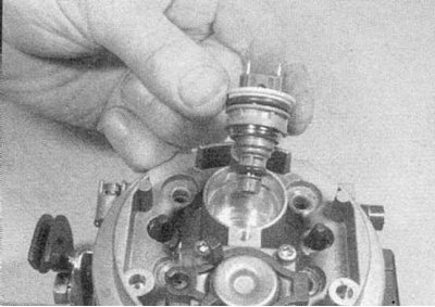
2. Note the location, then lift the injector and remove the o-rings (refer to accompanying illustration).
Installation
1. Install in reverse order. Keep the injector o-rings and caps in good condition. When installing the injector cover, make sure that the leads on the injector are correctly connected to the terminals in the cover, the terminals are marked "+" And "-".
Fuel pressure control
1. The fuel pressure regulator is part of the top half of the throttle body. In the event of a malfunction, the entire throttle body must be replaced.
Inlet air temperature sensor
Removing
1. Remove the air filter assembly as described in Section Removal and installation - air filter assembly and intake ducts.
2. Disconnect the sensor's multi-pin connector.
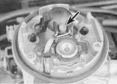
3. Loosen the fixing screw and release the sensor cover (refer to accompanying illustration).
4. Release the connecting tabs and remove the sensor along with the cover, wiring and connector.
Installation
1. Install in reverse order.
Idling stepper motor
Removing
1. Remove the air filter assembly as described in Section Removal and installation - air filter assembly and intake ducts.
2. Turn away screws of fastening of the case of a throttle. Carefully lift up the throttle body for better access to the motor.
3. Disconnect the multi-pin connector.
4. Turn away three fixing screws and get the motor.
Installation
1. Install in reverse order. Then perform the initial adjustment as follows.
2. Place a shim or feeler gauge approximately 5 mm thick between the throttle valve sector and the motor plunger. Turn the ignition on for a few seconds, then turn it off. Remove the gasket or dipsticks, then turn the ignition on and off again.
3. Start the engine and check that the idle speed and mixture quality are normal.
Throttle Potentiometer
1. The throttle potentiometer is part of the lower half of the throttle body. If it fails, the entire throttle body must be replaced. The idle control drive motor can be relocated from the old throttle body.
2. After replacement, the initial setting of the potentiometer must be checked using the Renault XR 25 diagnostic tester
Coolant temperature sensor
1. The coolant temperature sensor is located on the front of the thermostat housing. For information on removal and installation, see Chapter Cooling, heating system.
Electronic control module (ecu)
Removing
1. The electronic control module is located in the front right corner of the engine compartment.
2. Before removing the module, disconnect the earth cable from the battery.
Attention! If the car radio in your car is coded, make sure you know the code before disconnecting the battery.
3. Unscrew the bracket from the top of the electronic control module and release the belt. Alternatively, the bracket can be left on the module until the assembly is removed.
4. Loosen the mounting screws and remove the electronic control module and bracket (refer to accompanying illustration).
5. Disconnect the wiring connector from the control module.
Installation
1. Install in reverse order.
Pipe pressure sensor
Removing
1. The sensor is installed on the left side of the bulkhead of the engine compartment.
2. Disconnect the wiring from the sensor.
3. Turn away fixing nuts and remove the gauge.
Installation
1. Install in reverse order.
Fuel injection relay and priming pump relay
Removing
1. These relays are located on the fuse/relay box in the engine compartment (relay "J" And "L").
2. Remove the cover from the block.
3. Remove the desired relay.
Installation
1. Installation is carried out in the reverse order.
Speed/Crankshaft Position Sensor
Removing
1. The sensor is mounted on top of the transmission case.
2. Before removing the sensor, disconnect the ground cable from the battery (contact the head Engine electrical equipment for Scenic models), then remove the air filter cover as described in Section Removal and installation - air filter assembly and intake ducts.
3. Trace the wiring from the sensor to the connector and disconnect it from the main harness.
4. Turn away bolts of fastening and remove the gauge.
Installation
1. Install in reverse order. Tighten the sensor mounting bolts securely - note that only special bolts should be used; these bolts accurately mount the transducer, providing the correct air gap between the handpiece and the flywheel/drive plate.
Inertial fuel cut switch
Removing
1. The inertial switch is located on the left side of the engine compartment.
2. Turn away and remove screws of fastening of the switch, then disconnect electroconducting and remove the switch.
Installation
1. Installation is carried out in the reverse order. Finally, reset the switch by pressing the button.
Power steering pressure sensor
Removing
1. The pressure sensor is screwed into the power steering supply pipe from the pump to the steering gear.
2. To remove the switch, disconnect the wiring connector.
3. Wipe the area around the switch, then unscrew the switch and remove it from the pipe. Seal the hole in the pipe to prevent fluid leakage and dirt from entering the hydraulic system.
Installation
1. Installation is carried out in the reverse order. Finally, check the fluid level in the power steering system as described in Section Schedule of ongoing maintenance.
Knock sensor
1. Contact the Head Engine electrical equipment.