
Hydraulic block
Before unscrewing the brake pipe connectors, disconnect the ground cable from the battery and do not connect it until you have bled the system. If this is not done, air may enter the hydraulic unit, which is very difficult to (in some cases not possible) pump. When disconnecting the battery on Scenic models, refer to Section Charge and launch systems.
Note. Before proceeding, see the Warning provided at the beginning of Section Bleeding the hydraulic system of the brakes. Plugs are required to seal the hydraulic unit couplers after the pipes have been disconnected.
Removing
1. Disconnect the ground cable from the battery (on Scenic models, refer to Section Charge and launch systems).
2. Engage the handbrake, then jack up the front of the vehicle and place it on axle stands. Remove the right front wheel.
3. Turn away fasteners and remove an insert of an arch of a wheel.
4. Release the mounting bracket and disconnect the electrical wiring connector from the base of the hydraulic unit.
5. Minimize fluid loss by placing a piece of polyethylene under the master cylinder reservoir cap.
6. Mark the locations of the brake pipes so as not to confuse them during installation. Loosen the union nuts and separate the pipes from the hydraulic block. Be prepared for liquid to come out. Seal block and tube openings with plugs to prevent dirt from entering and further loss of fluid.
Note. If the hydraulic unit couplings are not properly plugged, air may enter the hydraulic unit pump (see Warning at the beginning of this Section).
7. Turn away fixing bolts of the hydraulic block and remove assembly from an impellent compartment.
Installation
1. Install in reverse order, paying attention to the following:
a) Before connecting, make sure that the pipes and couplings of the hydraulic unit are filled with liquid (refer to section Bleeding the hydraulic system of the brakes). Install the tubes, each in the same socket, and tighten the union nuts as shown in Specifications effort.
- b) Make sure that the wiring connector is secured with a bracket.
- With) Bleed the brake hydraulic system as described in Section Bleeding the hydraulic system of the brakes, then connect the battery.
- d) Finally, have a Renault workshop check the operation of the ABS system using special diagnostic equipment.
Electronic control device
Removing
1. Follow the steps described in paragraphs 1-4 above.
2. Loosen and remove the hydraulic unit and bracket bolts, then gently pry the bracket away from the unit. Tie up the hydraulic block to the body so as not to stretch the brake lines.
3. Turn away screws of fastening, then take away the control unit from the hydraulic block and remove it from the car.
Installation
1. Install in reverse order.
Front wheel rotation sensor
Removing
1. Disconnect the ground cable from the battery (on Scenic models, refer to Section Charge and launch systems).
2. Engage the handbrake, then jack up the front of the vehicle and place it on axle stands. For easier access, remove the wheel.
3. Trace the wiring from the sensor, releasing it from all brackets and marking its location, and disconnect the connector.
4. Loosen and remove the mounting bolt and remove the sensor from the steering knuckle.
Installation
1. Clean the mating surfaces of the sensor and steering knuckle and apply a small amount of multipurpose grease to the steering knuckle hole.
2. Make sure the tip of the sensor is clean and place it in the steering knuckle. Install the mounting bolt and tighten it to the Specifications effort.
3. Route the sensor wiring, using the marks made when it was removed, and attach it with all brackets and ties. Connect the electrical connector, then lower the vehicle to the ground and tighten the wheel bolts to Specifications effort.
Rear wheel sensor - except Scenic models
Removing
1. Block the front wheels, then jack up the rear of the vehicle and place it on axle stands. For easier access, remove the wheel.
2. Trace the wiring from the sensor, releasing it from all brackets and marking its location, and unplug the connector.
3. Loosen and remove the mounting bolt and remove the sensor.
Installation
1. Clean the mating surfaces of the sensor and drum brake support plate, and apply a small amount of multipurpose grease to the sensor housing.
2. Make sure the tip of the sensor is clean and place it in the working position. Insert the mounting bolt and tighten it to the Specifications effort.
3. Route the sensor wiring, using the marks made when it was removed, and attach it with all brackets and ties. Connect the electrical connector, then lower the vehicle to the ground and tighten the wheel bolts to Specifications effort.
Rear wheel sensor - Scenic models
Removing
1. Block the front wheels, then jack up the rear of the vehicle and place it on axle stands. Remove the wheel.
2. Loosen and remove the sensor mounting bolt.
3. Trace the wiring from the sensor, releasing it from all brackets and marking its location, and disconnect the connector.
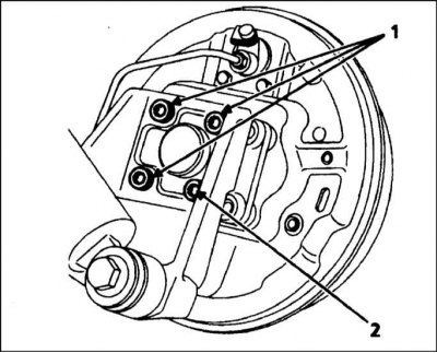
4. Loosen the four bolts securing the steering knuckle assembly to the lower suspension arm, then remove all but the lower rear bolt (refer to accompanying illustration).
Note. Installation will require new bolts.
5. Pull the drum/steering knuckle assembly out so that the sensor can be removed. It will probably be necessary to unscrew the remaining bolt almost to the end of the thread.
Installation
1. Clean the mating surfaces of the sensor and drum brake support plate, and apply a small amount of multipurpose grease to the sensor housing.
2. Make sure the tip of the sensor is clean and place it in the working position. Install the mounting bolt and tighten it to the Specifications effort.
3. Establish new bolts of fastening of a rotary fist and tighten them in a diagonal sequence given in Specifications effort.
4. Route the sensor wiring, using the marks made when it was removed, and attach it with all brackets and ties. Connect the electrical connector, then lower the vehicle to the ground and tighten the wheel bolts to Specifications effort.