
- place the car on a lift or raise the front of the car and install safety supports under the body;
- remove the protective cover of the power unit;
- remove the heat shields to gain access to the gearshift lever;
- turn on the first gear in the gearbox;
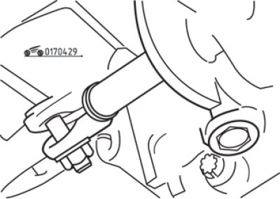
Pic. 4.29. Adjusting collar on the shift rod on the side of the gearbox
- loosen the clamp bolt on the gearshift shaft on the transmission side so that the shaft can move (pic. 4.29);
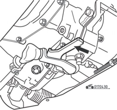
Pic. 4.30. Installing the B.Vi. 1133 (arrow)
- to hold the shift lever in the first gear position, install the B.Vi detent. 1133 (pic. 4.30). In the absence of such a tool, you can independently make a suitable replacement from a metal strip or piece of board;

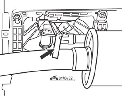
Pic. 4.31. Pull the latch down and rotate it 45° (the arrow shows the clamp bolt)
- at the same time pull the end of the template down and turn it at an angle of approximately 45°until it touches the groove on the gearbox housing (pic. 4.31);
Pic. 4.32. Gap adjustment 9.0 mm in the gearshift drive (the arrow shows the probe)
- move the shift lever so that a 9 mm thick flat feeler gauge can be inserted between the thrust ring on the lever and the wedge-shaped plate on the housing (pic. 4.32). In this position, tighten the bolt (see fig. 4.31);
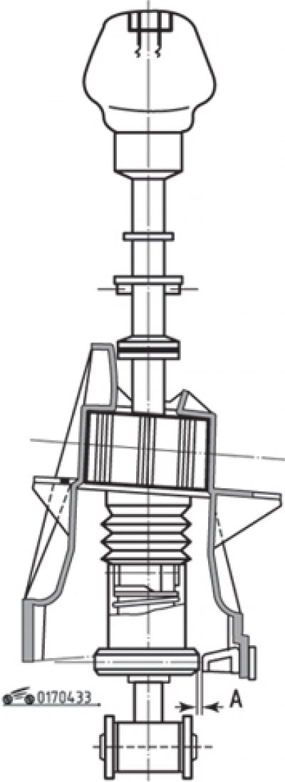
Pic. 4.33. Gap (A) between lever and body
- check the obtained gap A, which should be equal to 7–10 mm (pic. 4.33);
- remove the B.Vi template. 1133;
- check the correct gear engagement;
- install the protective pallet of the power unit;
- lower the car.