
Withdrawal procedure:
- under the car, unscrew and remove the eccentric bolt of the terminal connection of the universal joint yoke of the folding telescopic steering shaft, marking the relative position of the splined parts;
- slide the left front seat all the way back;
- dismantle the hood lock drive handle;
- remove the cover of the fuse block;
- on the front panel, remove the holder for the headlight range adjustment knob;
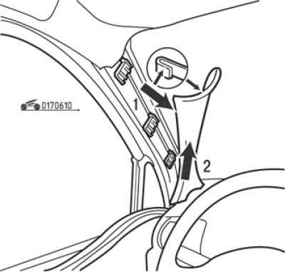
Pic. 6.10. Removing the windshield pillar trim: 1 - facing; 2 - overlay
- partially remove the left door seal and windshield pillar trim (see fig. 6.10);
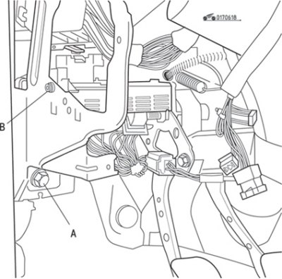
Pic. 6.18. Bolt (A) fixing the bracket of the central electronic switching unit and the bolt (IN) fastening of the central electronic switching unit
- remove the bolt securing the bracket of the central electronic switching unit and the bolt securing the central electronic switching unit (pic. 6.18);
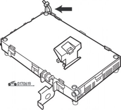
Pic. 6.19. Clamp for wiring harness on central electronics box
- remove clamp if necessary (pic. 6.19);
- partially release the central electronic switching unit;
- remove the air duct passing under the steering column;
Attention! To disconnect the air duct from the air distributor unit, you must first remove the opposite end of the air duct from the left vent nozzle.
- by turning the steering wheel, set the wheels of the car to a position corresponding to straight-line movement, and mark the position of the steering wheel with chalk;
- by turning the steering wheel, achieve free access to the bolt of the upper fastening of the folding shaft, then unscrew the bolt;
- according to the mark previously applied to the steering wheel, set the steering and the wheels of the car to the position of rectilinear movement;
- disconnect the fork of the lower cardan joint from the steering mechanism;
- disconnect the folding shaft from the steering column by pulling it down along the splines;
- disconnect the folding shaft from the steering gear by pulling it up;
- remove the folding shaft together with the corrugated cover;
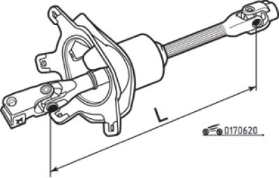
Pic. 6.20. Control dimension of the folding steering shaft: L= (363,6±1,5) mm
- check the distance between the axes of the crosses of the cardan joints of the shaft, which should be (363,6±1,5) mm (pic. 6.20). If the size is not within the specified limits, replace the folding shaft.
Installation order:
Pic. 6.17. Pass the string through the holes in the protective cover to install the cover on the motor shield
- tie the protective boot valves and the steering shaft universal joint yoke with twine (see fig. 6.17), push it into the opening of the motor shield;
Pic. 6.21. Installing the protective cover of the folding steering shaft in the engine compartment
- cut the string connecting the boot valves and the universal joint yoke, and install the boot on the bulkhead motor shield (pic. 6.21);
- install, without tightening, the eccentric bolt of the terminal connection of the universal joint fork;
- pulling up, put the spline of the folding shaft on the steering column;
- by turning the steering wheel, achieve free access to the bolt of the upper fastening of the folding shaft, then screw in the bolt;
- tighten the bolt of the upper fastening of the folding shaft to the specified moment, having previously lubricated its threaded part with a composition that prevents spontaneous unscrewing;
- orient the steering column along the wheels of the car and according to the mark on the steering wheel;
- tighten the eccentric bolt of the terminal connection of the universal joint yoke to the specified torque;
- install the air duct, the central electronic switching unit, the headlight corrector knob holder, the fuse box cover, the front pillar upholstery, the left door seal, the hood lock drive handle;
- check and, if necessary, adjust the toe-in of the front wheels.