



- elevated (compared to the usual) noise when engaging and disengaging the clutch;
- jerks when operating the clutch;
- incomplete clutch engagement (clutch "slips");
- incomplete disengagement of the clutch (the clutch "leads").
Note: If the clutch fails, we recommend replacing all of its components at the same time (driven and driving discs, clutch release bearing), since the work of replacing the clutch is labor-intensive, and the service life of undamaged clutch elements has already been reduced and, if they are reinstalled, the clutch may need to be replaced again after a relatively short mileage.
You will need: a key "11" (a socket head is more convenient), screwdriver...
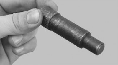
...mandrel for centering the driven disk (can be made from the primary shaft of the gearbox by removing the gears). A commercially available mandrel for front-wheel drive VAZ vehicles will also work.
1. Remove the gearbox (see "Removal and installation of the gearbox").
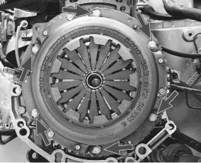
Note: This is how the bolts that secure the clutch housing to the engine flywheel are located.
Note: If you are going to install the old pressure plate, mark it in any way (for example, with paint) the relative position of the disc casing and the flywheel to set the pressure plate to its previous position (to maintain balance).
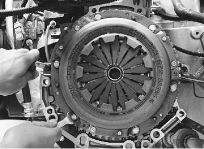
2. Hold the flywheel with a screwdriver (or a mounting blade) from turning, unscrew the six bolts securing the clutch pressure plate housing to the flywheel. Loosen the bolts evenly: each bolt by one turn of the wrench, moving from bolt to bolt by diameter.
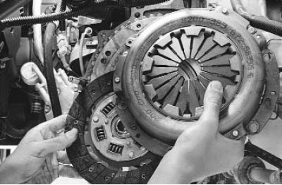
3. Remove the pressure and driven clutch discs from the flywheel, holding the driven disc.
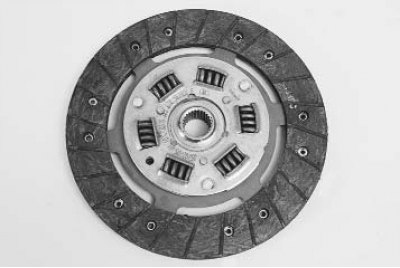
4. Inspect the driven clutch disc. Cracks on the driven disc parts are not allowed. Check the degree of wear of the friction linings. If the rivet heads are sunk less than 0.2 mm, the surface of the friction linings is oily or the rivet joints are loose, the driven disc must be replaced.
Note: If the driven disk linings are oily, check the condition of the gearbox input shaft seal. It may need to be replaced.
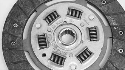
5. Check the reliability of the damper springs in the sockets of the driven disk hub by trying to move them by hand in the sockets of the hub. If the springs move easily in the sockets or are broken, replace the disk.
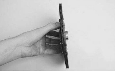
6. Check the runout of the driven disk if its warping is detected during visual inspection. If the runout exceeds 0.5 mm, replace the disk.
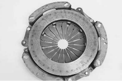
7. Inspect the working friction surfaces of the flywheel and pressure plate, paying attention to the absence of deep scratches, nicks, nicks, obvious signs of wear and overheating. Replace defective units.
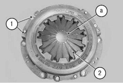
8. If the riveted joints 1 of the casing parts and the pressure plate are loose, replace the pressure plate assembly. Assess the condition of the diaphragm spring 2 of the pressure plate by visual inspection. The presence of cracks on the diaphragm spring is not allowed. The contact points of the spring petals with the clutch release bearing must be in the same plane and have no obvious signs of wear (wear should not exceed 0.8 mm). Otherwise, replace the pressure plate assembly.
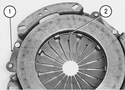
9. Inspect the connecting links 1 of the casing and the disc. If the links are deformed or broken, replace the pressure plate assembly. Assess the condition of the support rings 2 of the pressure spring by visual inspection. The rings should not have cracks or signs of wear. Otherwise, replace the pressure plate assembly.
10. Before installing the clutch, check the ease of movement of the driven disk along the splines of the primary shaft of the gearbox. If necessary, eliminate the causes of jamming or replace defective parts.
11. Apply high-melting grease to the splines of the driven disk hub.
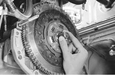
12. When installing the clutch, first install the driven disk using a mandrel...
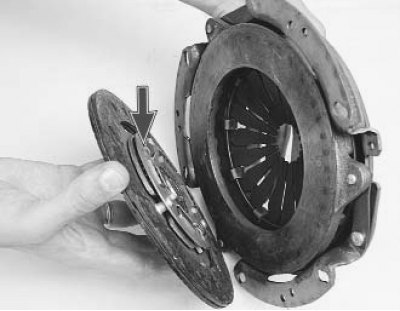
Note: Install the driven disc so that the protruding part of the disc hub (shown by arrow) was directed towards the diaphragm spring of the clutch housing.
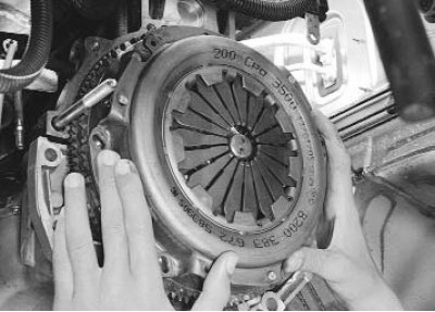
13. ...and then onto the three centering pins - the pressure plate casing and screw in the bolts securing the casing to the flywheel. Screw in the bolts evenly, one turn of the key each, moving alternately from bolt to bolt by diameter. The tightening torque of the bolts is 12 N·m (1.2 kgf·m).
14. Remove the mandrel and install the gearbox.
15. Install the lower end of the clutch release cable to the gearbox and adjust the length of the threaded end of the cable (see "Replacing and adjusting the clutch release cable").