
Removal
- When removing the box, you must use a Tav ball joint remover. 476.
- Also, when removing the power unit, you must use the following equipment:
- impact puller of ball joints;
- a rack to support the engine;
- jack;
- safety cushions for two-post lift levers.
- Place the vehicle on a two post lift.
- Disconnect the wires from the battery terminals and remove the battery.
- Remove the front wheels.
- Remove the engine sump and left front wheel arch liner protection.
- Drain the transmission oil from the gearbox.
- Reinstall the drain plug with a new gasket.
On the right side of the car
- Remove the front right floating brake caliper bracket and secure it to the suspension spring to protect the brake hose from damage.
- Remove the two bolts securing the drive shaft intermediate support to the support bearing.
- Using the Tav puller. 476 remove the tie rod end.
- Disconnect the wire from the brake pad wear sensor.
- Disconnect the wire from the wheel speed sensor.
- Unscrew the bolts of the lower fastening of the shock absorber strut to the steering knuckle.
- Remove the wheel speed sensor if the vehicle is equipped with an ABS system.
- Loosen the lower ball joint tip nut as much as possible and press the tip out of the steering knuckle using a ball joint impact puller.
- Remove the drive shaft - steering knuckle - brake disc assembly. Do not damage the corrugated covers of the drive shafts
On the left side of the car
- Remove the floating brake caliper bracket and attach it to the suspension spring.
- Remove the three bolts securing the drive shaft corrugated boot.
- Using the Tav puller. 476 remove the tie rod end.
- Disconnect the wire from the brake pad wear sensor.
- Disconnect the connector from the wheel speed sensor.
- Remove the bolts from the lower mounting of the shock absorber strut to the steering knuckle.
- Disconnect the tie rod ends and lower ball joints from the steering knuckles.
- Remove the hub - drive shaft - steering knuckle - brake disc assembly.
- Disconnect «massive» tire from the gearbox.
- Disconnect the engine speed and crankshaft position sensor connector located at the rear of the transmission.
- Remove the stopper and partially release the gear selection cable.
- Remove the 2 bolts and disconnect the clutch slave cylinder from the gearbox.
- Remove the bolt (1, fig. 6.24) tie rod fastenings and loosen the bolt (2).
- Disconnect the connector from the reverse light switch and remove the clamp securing the wiring harness to the transmission.
From below the car
- Disconnect «massive» engine tire located next to the oil filter cover.
- Loosen the tension, but do not remove the bolt securing the power steering pipe holder and remove the pipes from the holders.
- To facilitate access to the starter mounting bolts, remove the speed and crankshaft position sensor.
- Remove the starter heat shield.
From above the car
- Release the oil cooler without disconnecting the hoses from it and secure it to the engine.
- Install a self-made engine cooling radiator shield (pic. 6.25).
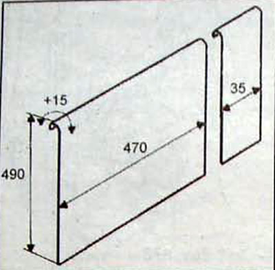
Pic. 6.25. Dimensions of the protective screen of the radiator of the cooling system
- Remove the air filter, the air duct located between the air filter and the turbocharger, and the air filter mounting bracket.
- To facilitate access to the bolts securing the clutch housing to the engine block, remove the rigid tube located between the air-to-air heat exchanger and the intake manifold
- Remove the air duct located between the turbocharger and the air-to-air heat exchanger.
- Remove the three air filter bracket holders.
- Unscrew the bolts securing the power steering pipes to the clutch housing, located behind the clutch release fork.
- Remove the gear shift cable mounting bracket and remove the cable end from the ball head of the gear shift lever.
- Pass the control cable over the coolant hose to prevent it from twisting when disconnected from the transmission.
From the lower left side of the car
- Remove the bolts securing the clutch housing to the engine cylinder block and the bolts securing the starter.
- Relieve the engine mount by installing a support stand with a rubber cushion under the oil pan.
- Unscrew the bolt securing the left pendulum suspension support to the cushion
- Remove the spring holder and remove the gear selection cable.
- Place a jack on the bottom of the transmission.
- Lower the power unit slightly to make it easier to remove the 4 bolts securing the left transmission mount (Figure 6.26).
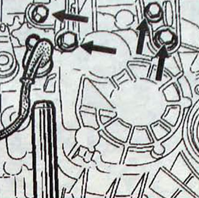
Pic. 6.26. Location of the left gearbox support bolts
- Remove the remaining bolts securing the clutch housing to the engine cylinder block. All bolts are the same length.
- With an assistant, remove the transmission from the vehicle.
Installation
- Make sure there are installation sleeves in the clutch housing housings.
- First, install and tighten the bevel head bolt of the left powertrain mount.
- Lubricate the end surface of the right drive shaft intermediate support bearing to prevent «sticking» parts until the next removal.
- Correctly attach the gear selector cable sheath to the left holder of the air filter mounting bracket. If the shell is not secured correctly, noise may occur while the vehicle is moving.
- Further installation is carried out in the reverse order of removal.
- Replace the brake caliper floating caliper guide pin bolts and tighten them to the specified torque.
- Press the brake pedal several times to set the brake cylinder pistons to their operating position.
- Tighten all nuts and bolts to the specified torques.
- Pour transmission oil into the gearbox.
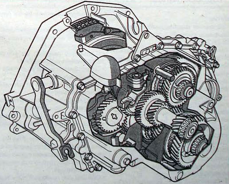
Pic. 6.27. Gearbox gears RK1
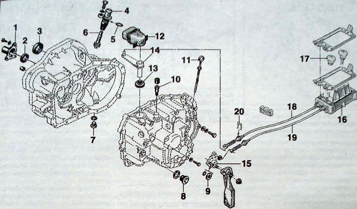
Pic. 6.28. Crankcases and gear shift mechanism of the RK1 gearbox: 1 - bearing guide sleeve; 2 - gearbox input shaft oil seal; 3 - left drive shaft oil seal; 4 - speedometer drive; 5 - sealing ring; 6 - speedometer drive gear; 7 - transmission drain plug; 8 - plug for filling/checking the transmission fluid level; 9 - gear selector rod seal; 10 - breather; 11 - dipstick for measuring the engine oil level; 12 - elastic protective coupling; 13 - clutch release rod seal; 14 - gear shift lever; 15 - gear selection lever; 16 - base; 17 - gear shift knob; 18 - gear shift cable; 19 - gear selection cable; 20 - cable clamp
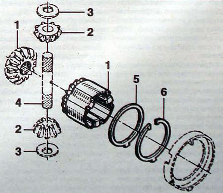
Pic. 6.29. Gearbox differential RK1: 1 - semi-axial gear; 2 - satellites; 3 - satellite support washers; 4 - satellite axis; 5 - adjusting washer; 6 - retaining ring