
Removal
- When removing the gearbox, the following special tools must be used:
Tav ball joint remover. 476;
bits for knocking out elastic pins Bvi. 31-01.
- Also, when removing the power unit, you must use the following equipment:
- impact puller of ball joints;
- a rack to support the engine;
- jack;
- safety cushions for two-post lift levers
- Place the vehicle on a two post lift.
- Disconnect the wires from the battery terminals and remove the battery.
- Remove the front wheels.
- Drain the gearbox oil.
- Install the drain plug with a new gasket.
- Be sure to install a protective screen made by yourself on the radiator of the cooling system. To make the screen, use an aluminum or steel sheet with a curved top edge to hang on the top of the radiator.
- Remove:
- engine sump protection;
- front wheels;
- front right and left wheel arch protective covers;
- mudguards.
- Remove the clamps securing the power steering pipes to the engine.
- Unscrew the fastening bolt «mass» tires on the gearbox.
- Remove the jet rod.
- Move the boot to the side and disconnect the shift rod from the transmission.
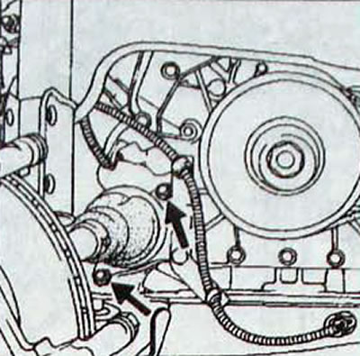
- Knock out the elastic pin of the right drive shaft (pic. 6.8).
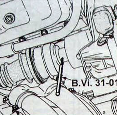
Pic. 6.8. Using the B.Vi.31-01 punch to drive out the elastic pin of the right drive shaft
- Remove the wiring harness holder on the transmission housing.
- Disconnect the connector from the reverse light switch, the oxygen concentration sensor and the wire from the starter.
- Disconnect the flexible speedometer drive shaft from the gearbox.
- Remove the exhaust pipe.
- Unscrew the bolts and remove the starter.
From below the car
- Remove the extension between the engine and the gearbox by unscrewing the bolts on the cylinder block and the bolts securing the clutch housing cover.
In the engine compartment
- Remove the air filter.
- Remove the fastening bolt «mass» tires on the gearbox.
- Remove the air filter mounting bracket.
- Remove the top dead center sensor.
- Disconnect the clutch release cable from the gearbox
- Remove the upper bolts securing the clutch housing to the engine cylinder block.
- Raise the engine by placing a support stand or jack under the engine block.
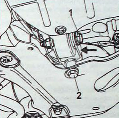
- Remove the transmission mount mounting bolts, but do not remove the top nut (pic. 6.9).
- Tilt the power unit slightly while lifting the vehicle (or lowering the support if it has variable rigidity).
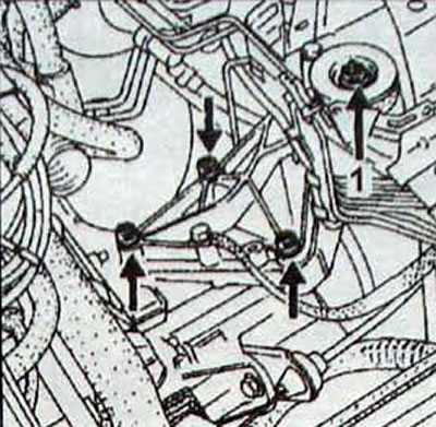
Pic. 6.9. Location of bolts and nuts (1) transmission mount mountings
From below the car
- Unscrew the nut located on the final drive housing.
- Place a jack under the gearbox
- Raise the transmission slightly with a jack and unscrew the two bolts securing the rear engine mount and move it. as far back as possible.
- Disconnect the transmission from the engine and lower it using a jack. moving the engine mount if necessary.
Installation
- Make sure. that the installation sleeves are inserted into the gearbox sockets.
- Lubricate the splines of the right side gear with MOLYKOTE BR2 grease
- Check the position of the clutch release bearing - protrusion (A. fig. 6.10) must be inserted into the groove of the clutch fork.
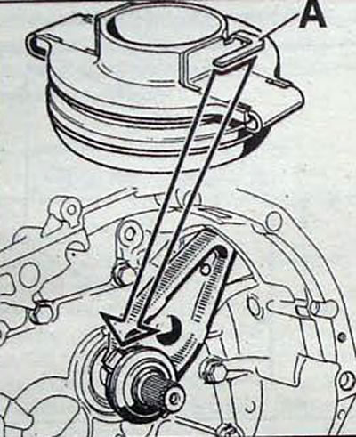
Pic. 6.10. Installing the clutch release bearing on the guide sleeve: A - protrusion
- The JC gearbox has a grease-filled case to support the clutch release fork. Before installing the fork, put MOLYKOTE BR2 lubricant in the case (pic. 6.11).
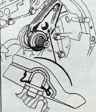
Pic. 6.11. Location of the cover for supporting the clutch release fork, filled with lubricant (JC gearbox)
- Install the gearbox
- Make sure. that the locating sleeves are correctly seated in the sockets on the engine block.
- Check the presence of a centering sleeve, which must be located in the hole for the starter mounting bolt (V. fig. 6.12).
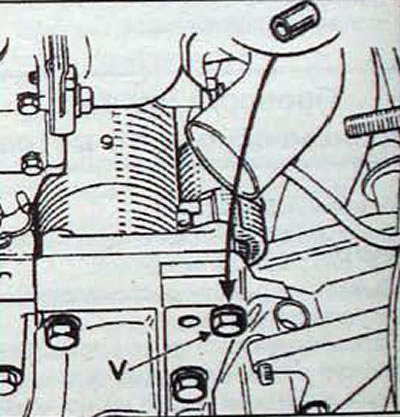
Pic. 6.12. Location of the centering sleeve under the bolt (V) when installing the starter
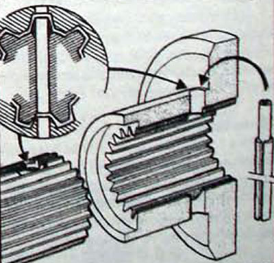
Pic. 6.13. Aligning the holes in the drive shaft and side gear to install the elastic pin
- Using a jack, position the power unit so that the left front engine mount can be installed
- Install the drive shaft against the side gear.
- Rotate the steering knuckle and insert into the side gear, using the angular bit B. Vi 31-01 to align the holes for the elastic pins. The entrance chamfer of the hole in the side gear makes it easier to install a new elastic pin. Apply RHODORSEAL 5661 to seal the ends of the pins.
- After installing the power unit on the car, check the travel of the clutch release fork, which should be within 26-28 mm (pic. 6.14).
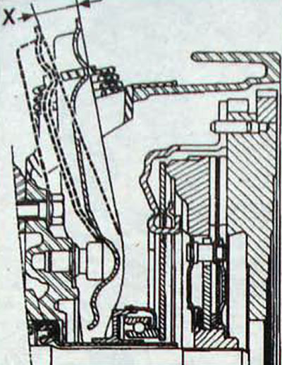
Pic. 6.14. Place for measuring the clutch release fork stroke: X = 26-28 mm
- Pull the clutch cable in the area of the clutch release fork on the gearbox and check the free play of the cable, which should be at least 3 cm. This check shows that the automatic wear compensation mechanism is working properly.
- Replace the brake caliper floating caliper guide pin bolts and tighten them to the specified torque.
- Press the brake pedal several times to set the brake cylinder pistons to their operating position.
- Tighten all nuts and bolts to the specified torques.
- Pour transmission oil into the gearbox.
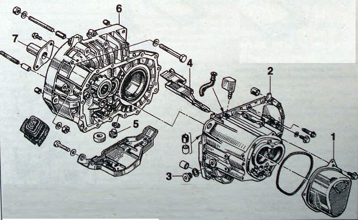
Pic. 6.15. JC5 gearbox housings:1 - 5th gear cover; 2 - gear housing; 3 - filling/checking transmission oil level plug; 4 - channel for oil supply; 5 - transmission oil drain plug; 6 - clutch housing; 7 - clutch release bearing guide sleeve
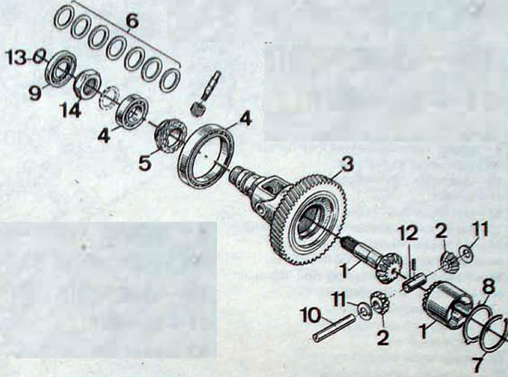
Pic. 6.16. JC5 gearbox differential: 1 - lunar gear; 2 - satellites; 3 - driven gear of the main gear; 4 - tapered bearing; 5 - speedometer drive gear; 6 - adjusting washers; 7 - retaining ring; 8 - adjusting washer; 9 - oil seal; 10 - satellite axis; 11 - satellite support washers; 12 - spacer sleeve; 13 - seal; 14 - nut
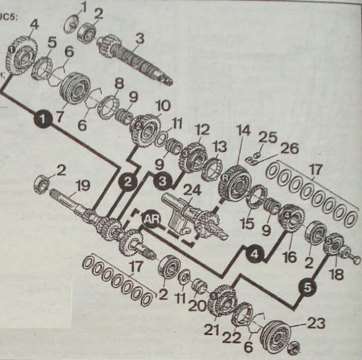
Pic. 6.17. JC5 gearbox gears: 1 - ring; 2 - roller bearing; 3 - secondary shaft; 4 - 1st gear gear; 5 - 1st gear synchronizer ring; 6 - spring; 7 - 1st/2nd gear synchronizer; 8 - 2nd gear synchronizer ring; 9 - needle bearing; 10 - 2nd gear gear; 11 - washer; 12 - 3rd gear gear; 13 - 3rd gear synchronizer ring; 14 - reverse gear and 3rd/4th gear synchronizer; 15 - 4th gear synchronizer ring; 16 - 4th gear gear; 17 - adjusting washers; 18 - 5th gear gear; 19 - input shaft; 20 - needle bearing; 21 - 5th gear gear; 22 - blocking ring of the transmission gear synchronizer; 23 - 5th gear synchronizer; 24 - intermediate gear and reverse gear shaft; 25 - locking roller; 26 - clamp spring
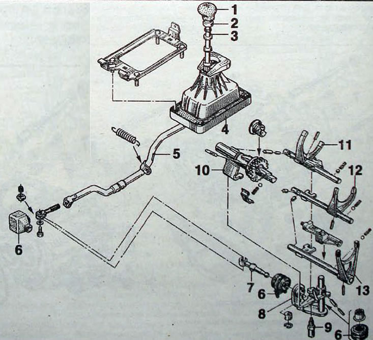
Pic. 6.18. JC5 Gearbox Shift Mechanism: 1 - gear shift knob; 2 - reverse gear lock ring; 3 - gear shift lever; 4 - base; 5 - gear shift rod; 6 - elastic protective coupling; 7 - rod; 8 - gear selection mechanism; 9 - axis; 10 - 5th gear selection mechanism; 11 - 1st/2nd gear shift fork; 12 - 3rd/4th gear shift fork; 13 - 5th gear shift fork
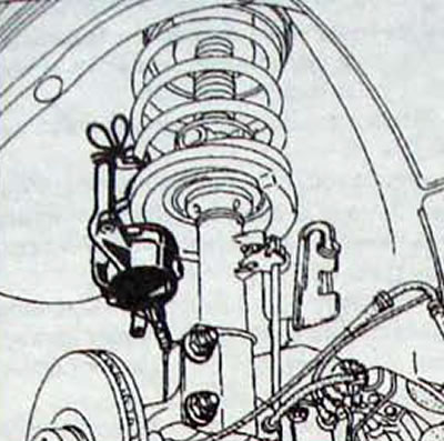
Pic. 6.19. Attaching the brake caliper bracket to the front suspension spring
Pic. 6.20. Location of bolts securing the intermediate support of the drive shaft in the support bearing
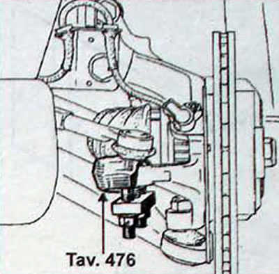
Pic. 6.21. Using the Tav puller. 476 to disconnect the tie rod end from the steering knuckle
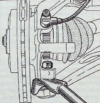
Pic. 6.22. Using an Impact Puller to Press Out the Lower Ball Joint
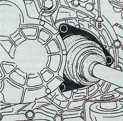
Pic. 6.23. Location of bolts securing the corrugated boot of the drive shaft to the differential flange
Pic. 6.24. Bolt location (1) tie rod and bolt fastenings (2)