



Contents: Removal 🠛 Installation 🠛
Due to the large size of the steering gear, to remove it, it is necessary to disconnect the sub-engine frame from the body using a set of special tools T. Av. 1233-01, while the steering gear is removed through the left wheel arch.
Please note: The steering gear and power steering pump cannot be repaired.
Removal
- Disconnect the cable from the negative battery terminal.
- Set the vehicle wheels to move straight ahead.
- Raise the car.
- Remove the wheels and the left wheel arch liner.
- Using the T. Av. 476 puller, disconnect the ball joint of the steering rod end from the steering knuckle.
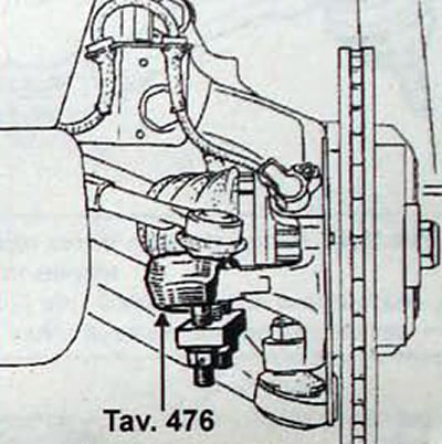
Fig. 9.9. Using the Tav. 476 puller to disconnect the tie rod end from the steering knuckle
- Loosen the nuts securing the lower ball joint pins of the anti-roll bar struts.
- Loosen the nuts securing the ball joint pins of the lower arms of the front suspension.
- On vehicles with Z and G engines, remove the exhaust system intake pipes from the exhaust manifold to the catalytic converter. Unscrew the nut and remove the torque rod mounting bolt.
- On vehicles with F engines, move the boot aside, unscrew the bolt securing the end of the drive rod to the gear selector lever and remove the gear shift rod.
- On vehicles with all engines, remove the nut and bolt connecting the steering shaft universal joint fork.
- Use a special device to lock the steering wheel to prevent the position of the contact ring from changing.
- Remove the two bolts securing the brake hose holders, the brake pad wear indicator lamp wire and the ABS sensor.
- On the left side of the vehicle, disconnect the ABS sensor connector and the brake pad wear indicator lamp wire from the holders
- Disconnect and release the ABS sensor and brake pad wear indicator lamp wires from the holders on the subframe.
- Place a jack under the engine subframe.
- Remove the sub-engine frame reinforcements and successively replace its mounting bolts with T. Av. 1233-01 threaded rods.
- Using the T. Av. 1233-01 tool, loosen the nuts so that the sub-engine frame drops by 4-5 cm
- Remove 2 bolts and heat shield from brake lines.
- Release the brake pipe and ABS wire from the holders at four points.
- Disconnect the power steering lines.
- To disconnect the power steering pipes on vehicles with Z engines, use the Dir. 1282-01 and Dir. 1282-02 keys, passing them through the wheel arch.
- On vehicles with Z and G engines, release the power steering heat exchanger pipe.
- Lower the engine subframe another 8 cm.
- Remove the steering gear heat shield.
- Unscrew the 4 nuts securing the steering gear housing (Fig. 9.10).
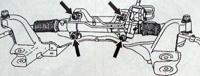
Fig. 9.10. Location of the steering gear housing mounting nuts
- Remove the steering gear assembly with rods by pulling it through the left wheel arch
Attention
When handling the steering gear, observe the following safety precautions:
- do not hold the steering gear by the covers;
- do not transfer the steering gear by the pipes;
- protect the steering gear brackets from impacts;
- protect steering rods from impacts.
When replacing the steering gear, save the tie rod ends for future use. Loosen the tie rod end clamp bolt one turn. Measure the size from the tie rod hexagons to the tie rod ends and loosen the tie rod ends (Fig. 9.11).
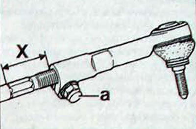
Fig. 9.11. Location of measurement of dimension (X) from the hexagon of the steering rod to the tip of the steering rod: a - clamping bolt for fastening the steering rod end
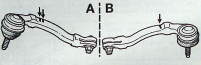
Fig. 9.12. Location of identification marks for the installation side of the steering rod ends: A - left steering rod end (2 cast marks); B - right steering rod end (1 cast mark)
Installation
- Installation is carried out in the reverse order of removal, taking into account the following.
- When screwing on the tie rod ends, ensure equal dimensions (X. Fig. 9.11) from tie rod ends to tie rod ends
- When installing, it is necessary to use new steering gear housing mounting nuts.
- Install the steering gear on the subframe and the Dir. 1303-01 device for adjusting the position of the steering gear (Fig. 9.13).
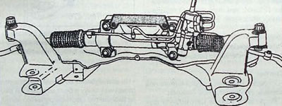
Fig. 9.13. Installing the Dir. 1303-01 device for locking the steering gear on the subframe
- With the Dir. 1303-01 tool installed, tighten the four steering gear mounting nuts to the specified torque.
- Install a heat shield.
- Before installing the subframe, connect the power steering lines and tighten their fittings to the required torque, since after installing the subframe, access to the fittings will be difficult.
- Each time the subframe is removed, replace all subframe mounting bolt nuts and be sure to adhere to the required tightening torques.
Note: Two washers (1, Fig. 9.14) on the rear supports of the sub-engine frame ensure the centering of the sub-engine frame assembly with the front suspension relative to the body when they are attached to the body. Therefore, be sure to ensure the correct position of these washers, starting to tighten the sub-engine frame fastening parts from the left rear fastening point.
- Since the lower part of the steering column can move, it is necessary to adjust the position of the steering shaft universal joint yoke relative to the steering gear drive pinion.
- In the car interior, install the Dir. 1408 (fig. 9.6).
- Screw in the steering shaft cardan joint yoke connection bolt and tighten the bolt nut to the required torque.
- Remove the Dir. 1408 tool.
- Fill the tank three-quarters full.
- With the engine running, slowly turn the steering wheel from lock to lock.
- Check the system for leaks and add fluid to the required level.
- Check the front wheel alignment and adjust the toe-in if necessary.