
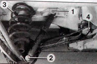
Pic. 11.1. Rear suspension elements: 1 - upper shock absorber mount; 2 - lower shock absorber mount; 3 - cylindrical spring; 4 - attaching the trailing arm to the body
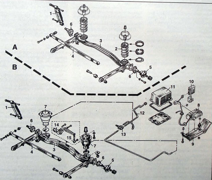
Pic. 11.2. Rear suspension:A - mechanical (classical) suspension; B - controlled suspension; 1 - shock absorber; 2 - spring; 3 - rear beam; 4 - Panhard transverse rod; 5 - rear wheel hub; 6 - rear wheel hub axle; 7 - air spring; 8 - compressor block; 9 - protective cover; 10 - electronic control unit; 11 - cover; 12 - pipes; 13 - tee; 14 - height sensor; 15 - height sensor rod
Mechanical suspension
Springs
Even-pitch coil springs are installed on the rear shock absorbers.
Deflection when applying a force of 100 kg, mm:
- unloaded car - 20
- loaded car - 14
Electronically controlled vehicle height control
Air springs
Rubber coil springs are installed instead of coil springs.
Deflection when applying a force of 100 kg, mm:
- unloaded car - 33
- loaded car - 20
Shock absorbers
Hydraulic telescopic shock absorbers convert body and suspension vibrations into heat, resulting in vibration damping. The principle of operation of the shock absorber is based on creating increased resistance to body swaying due to the forced flow of fluid through small flow sections in the valves.
Compressor
The compressor is combined into one unit with an electric motor. The operation of the compressor is controlled by an electronic control unit depending on the information transmitted by the level sensor.
The compressed air from the compressor is dehydrated, degreased and filtered. The air entering the system must be treated in the same way. to avoid damage to parts of the system mechanisms.
The compressor is located under the car to the right of the spare wheel in a soundproof box.
- Operating voltage, V - 12± 3
- Maximum current consumption, A - 24
- Rotation speed, min-1 - 1700-2700
- Volume, cm3 - 18.5
- Maximum operating pressure, bar - 11.5
- Lubrication system - dry sump
Exhaust solenoid valve
It is located on the compressor block and allows air to be released from the air springs if the rear of the vehicle is raised too high.
- Operating voltage, V - 12± 3
- Maximum current consumption, A - 0.8
Body position sensor
The inductive type sensor is located above the rear axle of the vehicle and is connected to it by a lever and rod. The role of the sensor is to determine changes in vehicle clearance and transmit information to the electronic control unit.
- Type - inductive
Electronic control unit
The pre-programmed electronic control unit is located inside the vehicle behind the rear left wheel.
Based on the signals received from the level sensor, the unit controls the vehicle's damping parameters through the springs and the solenoid valve block.
Rear wheel alignment angles
- Wheel camber — 1°±10° (not regulated)
- Toe - 0°20 "±10 " or 2.2±1.1 mm (not regulated)
Tightening torques, Nm
- Nut securing the front part of the trailing arm of the rear suspension beam - 90
- Panhard tie rod bolt nut - 60
- Nut of the upper shock absorber mounting - 60
- Nut of the lower shock absorber mounting - 25
- Air spring lower mounting bolt - 25
- Air spring upper mounting bolt - 50
- Hub fastening nut - 170
- Wheel bolts - 100
Attention. When installing most of the rear suspension components, compress the rear suspension with straps or load the vehicle until the measurement between the rear floor cross member and the floor is 408 mm (H5. pic. 11.3). This size is obtained on a car with approximately the following load: with five seats installed, a full fuel tank, and a payload of 50 kg. driver and three passengers in the cabin.
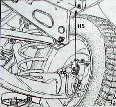
Pic. 11.3. Distance (H5) between the rear cross member of the body floor and the floor