
The pneumatic part of the system consists of the following elements:
- compressor unit (8, fig. 11.2);
- two air springs (7);
- tee (13) with valve;
- connecting pipelines.
The electrical part of the system consists of the following elements:
- control unit (4, fig. 11.9);
- body position sensor (5);
- malfunction warning lamp in the instrument cluster;
- three fuses;
- electrical wiring.
The compressor unit is located under the car on the right side of the spare wheel and is covered with a soundproof casing. The compressor unit does not require maintenance.
The node consists of the following elements:
- electric motor (1, fig. 11.6);
- compressor (2);
- air filter with granular desiccant (3);
- exhaust solenoid valve (4). Air springs replace the coil springs of the classic rear suspension and provide the connection between the suspension beam and the suspension. They have a movable stop (1. fig. 11.7), which is used when compressed air leaks.
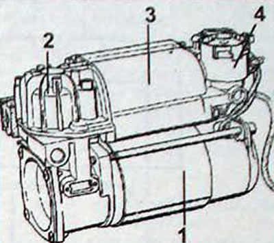
Pic. 11.6. Electronic height control compressor assembly: 1 - electric motor; 2 - compressor; 3 - inlet air filter with granular desiccant; 4 - exhaust solenoid valve
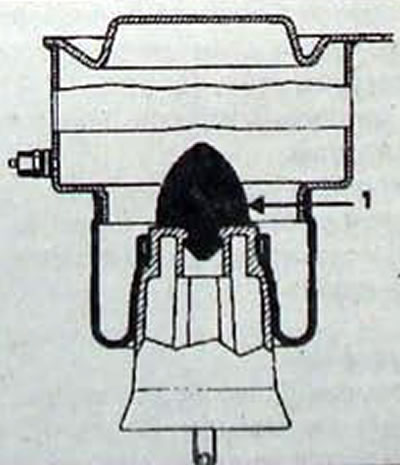
Pic. 11.7. Movable stop location (1) air spring
The control unit is located in the passenger compartment behind the right rear wheel arch next to the third seat belt inertia reel.
Operating principle
The body position sensor sends information about the height of the rear of the vehicle to the control unit.
Based on the information received, the control unit turns on the compressor or exhaust solenoid valve to restore the vehicle to the specified ground clearance
The control unit ensures the safety of the system by blocking it under certain conditions and warning the driver via a warning light in the instrument cluster, especially when there is a compressed air leak.
The sensor is attached to the suspension and is connected to the suspension beam through a linkage and lever.
Note. The rod length is set at the factory and should not be changed during operation.
The sensor transmits information to the control unit about the exact position of the vehicle body and detects vehicle movement by recording vibrations caused by the movement.
The system is programmed to maintain the height of the rear of the car at a given level, i.e. maintain the H5 size (rice. 11.3) measured between the rearmost floor cross member and the road surface:
- 412 mm with 195 mm tires;
- 422 mm with 205 mm tires.
This size corresponds to a constant vehicle ground clearance, regardless of load (at normal tire pressure).
The system does not take into account small fluctuations in vehicle height when driving, associated with suspension movements.
The system is brought into operation when one of the doors is opened or the ignition is turned on.
The power supply circuit of the compressor unit is interrupted within the first 10 seconds of vehicle movement.
Loading the car
If the clearance decreases by less than 5 mm, no adjustment is made as the system is within tolerance (this prevents spontaneous operation of the system).
If the clearance decreases by more than 5 mm. the compressor starts working after 2 s, increasing the pressure in the circuit and returning the car to normal ground clearance.
The system can adjust the ground clearance when the vehicle is moving when the ground clearance has decreased by more than 5 mm after 45 seconds (due to passenger movements in the cabin).
Unloading the car
If the clearance has increased by less than 5 mm, no adjustment is made, since the system is within tolerance (this prevents spontaneous operation of the system).
If the ground clearance has increased by 5 mm or more, after 2 s the exhaust solenoid valve opens and returns the car to normal ground clearance.
Notes. When performing any work on the pneumatic circuit, replace the O-rings of the pipelines (except for the pipeline connected to the compressor) and nuts, and hand-tighten pipe fittings. Before working on the system, release compressed air from it through the valve on the tee (pic. 11.8).
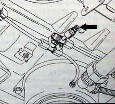
Pic. 11.8. Location of the valve on the tee to release air from the body height control system
Warning lamp
The warning lamp lights up for approximately 3 seconds to check the functionality when the ignition is turned on.
The indicator lamp lights up along with the symbol «Service» if the exhaust solenoid valve operates continuously for 80 seconds, the compressor operates more than 20% during the first hour, the compressor operates more than 6% during the subsequent hours, and an air leak is detected in the circuit (the compressor runs continuously for 180 s).
Security measures
The control unit automatically limits the continuous operation of the compressor to 180 seconds and the exhaust solenoid valve to 80 seconds.
The control unit automatically limits intermittent operation of the compressor to 20% during the first hour and to 6% during subsequent hours if the ignition is not turned off.
These restrictions are reactivated in the control unit when the ignition is turned on after the vehicle is stopped. If there is a significant leak of compressed air, the vehicle rests on the movable stops of the air springs. In this case, the vehicle speed should not exceed 40 km/h.
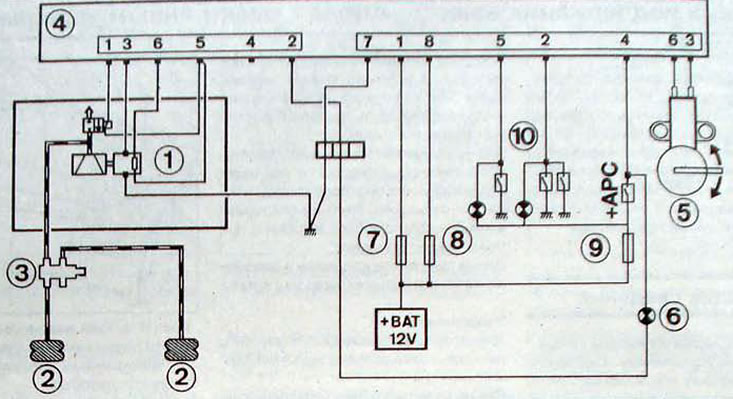
Pic. 11.9. Electrical diagram of the electronically controlled vehicle height control system:1 - compressor block; 2 - air springs; 3 - tee; 4 - control unit; 5 - body position sensor; 6 - malfunction indicator lamp; 7 - fuse F38 (30 A); 8 - fuse F50 (5 A); 9 - fuse F40 (20 A), 10 - door and tailgate limit switches