
4-cylinder petrol engines
2. Check the tension of the water pump belt at the point shown in the illustration. It also shows the power steering and air conditioning compressor drive belts. In Renault workshops, a special device is used to control the belt tension, but the tension can be checked without it. To do this, take the belt with your index and thumb and press it firmly down and up at the point «1». The deviation amplitude should not exceed 3.5 -4.5 mm, i.e. the belt must be tight enough. This value is for a new belt, when installed on a cold engine. With a warm engine, the deviation is 5.5 - 6.5 mm.
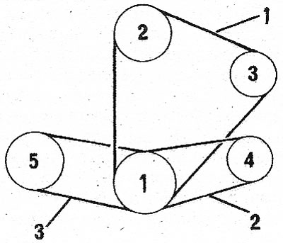
9.2 Location of drive belts on a gasoline engine. The circles represent the following components 1. Crankshaft; 2. Water pump; 3. Generator; 4. Power steering pump; 5. Compressor
3. The remaining belts must be checked on the basis of the following data, taking into account the difference between cold and warm engines:
At the point «2» (steering):
- Cold engine - 3.5 mm.
- Warm engine - 4.0-4.5 mm.
At the point «3» (compressor):
- Cold engine 3.0-4.0 mm.
- Warm engine 3.5-4.5 mm.
4. The installation method of the water pump and alternator belt is different for each engine group.
5. To install the belt on earlier models, loosen the guide nut and bolt and, using a special puller or screwdriver, press the generator out until tension is established.
6. Check the tension and tighten the bolt and nut. Also tighten both screws on the bottom of the generator.
7. Modern engines are equipped with a tensioner (see illustration). Bolt 1 is used to tension the belt of the two components. If power steering is installed, check the tension at the points shown in illustration 9.2 (between power steering pump pulley and crankshaft pulley).
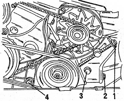
9.7 Alternator and power steering pump with tensioner installed. Bolt 1 is used to tension the alternator belt, bolt 2 is used to tension the power steering pump belt. The power steering pump is fixed with bolts 3 and 4
Diesel engine
8. The illustration accompanying this item shows all the belts that can be installed on a diesel engine, as well as the fuel pump timing belt.
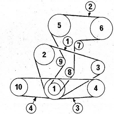
9.8 Location of drive belts on a turbocharged diesel engine. Check the tension of the water pump belt at point 1. The remaining points are indicated in the text 1. Crankshaft; 2. Water pump; 3. Generator; 4. Power steering pump; 5. Camshaft; 6. Fuel pump; 7. Timing belt tensioner; 8. Support roller; 9. Support roller; 10. Compressor
9. The tension of the water pump and alternator belt is controlled at point 1 and must correspond to the value specified in the Specifications for the gasoline engine for both cold and warm.
10. To tension the belt, refer to illustration 9.2; on earlier models, the movement of the belt is regulated using guides, as on gasoline engines of early models. Bolt 1 is used to adjust the alternator. The V-belt is used to drive the generator and water pump. On early models, after removing the guides, the belt tension is adjusted by pressing the alternator out. 11 The process of tensioning the power steering pump belt is described in Section «Steering». This belt is located between pulleys 1 and 4 and its tension is measured at point 3. The following values are considered standard for individual components:
At point 3 (steering):
- Cold engine 4.0 - 4.5 mm.
- Warm engine 5.0 mm.
At point 4 (compressor):
- Cold engine 3.0 - 4.0 mm.
- Warm engine 3.5 - 4.5 mm.
12 To replace the water pump and alternator belt, the power steering pump belt must first be removed.
V6 engine
13. The attached illustration shows a drive belt installed on a V6 engine. A so-called V-belt is used to drive the water pump and generator.
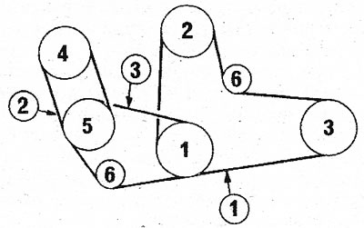
9.13 Location of drive belts on a V6 engine. All options shown 1. Crankshaft; 2. Water pump; 3. Generator; 4. Power steering pump; 5. Compressor; 6. Belt tensioner
14. The amplitude of the deflection of this belt must be checked at point 1. The deflection of the belt should be about 3 mm on a cold engine and, accordingly, 3.0 - 3.5 mm on a warm engine.
15. If the belt deflection is no more than 4.5 mm, no adjustment is required. Otherwise, loosen the tensioner to adjust and push inward, then tighten the tensioner again. Check tension after adjustment.
16. The tension of the remaining belts should be as follows:
At point 2 (steering):
- Cold engine 2.5 - 3.0 mm.
- Warm engine 3.0 - 3.5 mm.
At point 3 (compressor):
- Cold engine 3.0 - 4.0 mm.
- Warm engine 3.5 - 4.5 mm.
17. The procedure for replacing drive belts in most cases is quite laborious. To get to the mounting, it is necessary to remove the grille, the upper frame cross member and the radiator.
18. To replace the alternator belt on a diesel engine, first remove the power steering pump belt.
19. To replace the compressor drive belt on a 4-cylinder engine, remove the drive belt.
20. To replace the alternator belt on a V6 engine, first remove the power steering pump belt. Also remove the compressor belt if the model is equipped with air conditioning.
21. When replacing the power steering pump belt, also remove the compressor belt first.
22. Please note that certain drive belts may have mesh on the inside. If the belt is worn, torn, oily, or leaves particles on the pulleys, it must be replaced. When replacing the V-belt, clean the meshes on the inside of the pulleys well.