
Combined instrument panel Renault 19 RT
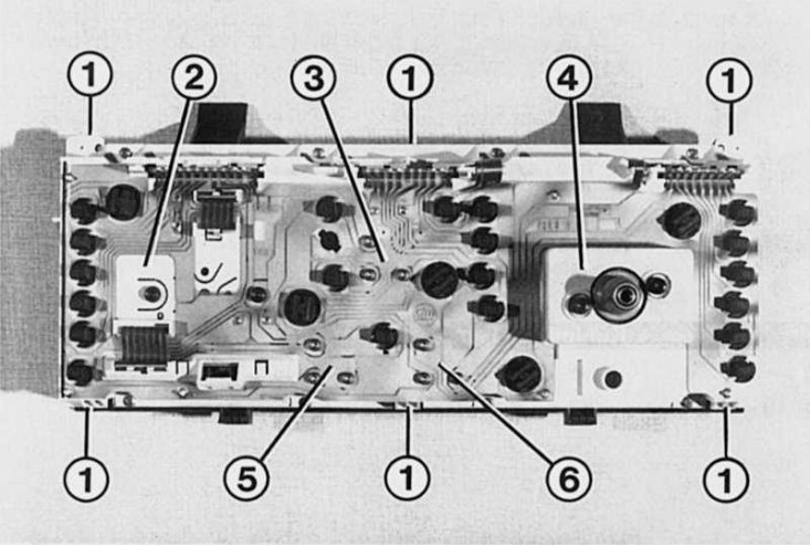
If you need to remove or replace any device, then after removing the board, release the case from the fasteners (1); 2 - tachometer; 3 - fuel level indicator in the tank; 4 - speedometer; 5 - oil level indicator; 6 - coolant temperature indicator.
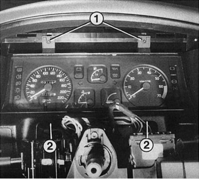
The figure shows with the dashboard screen removed, both upper fixing screws (1). Two bottom mounting screws (2) located behind the dashboard cutout. Once the screws have been removed, carefully pull the combined instrument towards you, but do not pull it out completely until the connectors and the speedometer shaft are disconnected.
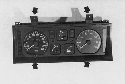
In order to make it clear how the combined instrument panel is attached, the attachment points of the upper and lower screws are shown here (shown by arrows). If the combined instrument panel needs to be dismantled, always place a soft cloth under its front side.
If a warning lamp is burned out, the combined instrument panel must be removed to replace it.
1. Disconnect a wire of weight from the storage battery.
2. Remove the steering wheel.
3. Disassemble the lower trim of the steering rack (4 screws T 20).
4. Remove the top facing of a steering rack. Wherein (if installed), carefully remove the radio remote control from the top.
5. Remove the bottom facing of the panel of devices (3 screws T 20).
6. Remove the top of the dashboard screen (2 screws).
7. Turn out the top screws of fastening (T10).
8. Turn out the bottom screws of fastening. To get to the necessary screws, it is necessary to remove the fastening of the ignition switch block. To do this, press the mount against the steering column and at the same time pull it forward.
9. Remove from below, behind the combined instrument, a shaft of a speedometer.
10. Carefully pull the combined instrument panel forward and disconnect the connectors.
11. Remove the combined instrument panel from the socket.
12. If necessary, disconnect the remaining connectors.
13. When assembling, make sure that the connectors and the speedometer shaft are correctly inserted or, accordingly, installed.
14. Before final assembly, check that all lamps are working!
Replacing indicator lamps
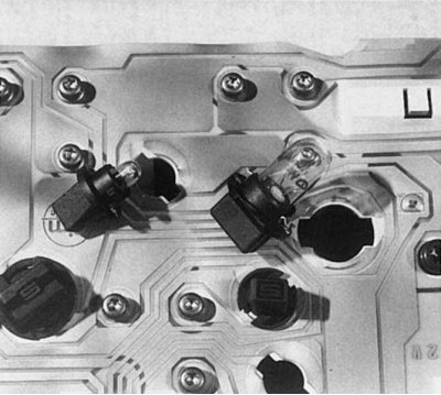
Replacing the bulbs on the combined instrument panel is carried out in the same way for all equipment variants. Incandescent lamps are located in plastic frames, which are fixed with a so-called bayonet closure on the combined instrument panel board. To replace the bulb, push the bulb slightly and then turn it counterclockwise and remove it from the socket. The auto parts store only sells bulbs with frames.
The indicator lamps as well as the instrument panel lamps are fixed in plastic frames on the back of the combined instrument panel. You will need 1.2W or 3.0W bulbs for replacement.
1. With the combined instrument panel removed, remove the bulb holder to be replaced by turning it counterclockwise.
2. Incandescent bulb must be replaced along with the frame.
Removing appliances
All control lamps and indicators in the combined instrument panel are supplied with electricity through a circuit board on which the wiring diagram is printed. There are different types of boards for different modifications - remember this when buying at an auto parts store. Replacing the board is a fairly voluminous job.
Therefore, it should only be carried out by experienced motorists, since it will be necessary to solder a large number of wire jumpers and electronic components. The most important tool for this is a clean soldering iron and soft solder for electronics. An inexperienced car enthusiast should run at least a few test solders on some old radio.
1. Remove the combined instrument panel.
2. Carefully unscrew all screws and disconnect all contacts (depending on the configuration of fuel level indicators, coolant temperature and speed).
3. Remove all bulbs by turning counterclockwise (bayonet mount).
4. Use a soft cloth to avoid scratching the Plexiglas screen on the front of the combined instrument panel.
5. Unsolder all jumper wires and electronic components. To do this, make an accurate sketch of the location of all elements in advance, and for electronic elements, also the exact position of their installation.
6. Carefully remove the board.
7. Install the new board and fix it with the screws on the combined instrument panel.
8. Solder jumper wires and electronics as planned.
9. Before final installation, check all functions of the combined instrument panel.