
Minus in «mass»
Electric current can only flow in a closed circuit. If you turn on the switch at home, the light comes on.
The same thing happens in the car; from the battery or generator, the electrical current flows through the appropriate consumers, back to the battery or generator.
Most current consumers in the Renault 19 have two wires attached. But only one of them goes directly to the battery or, respectively, to the three-phase alternator. The other wire is, in most cases, screwed to the steel sheet of the body.
You should be aware that the metal parts of the body, engine and, accordingly, the gearbox also conduct electricity. In automotive electronics, they are referred to by the term «weight». They provide the return of current to the negative pole of the battery. Rule to remember: minus in mass.
If the current consumer is located directly on the metal, then it needs only one connecting wire, but in today's plastic-rich car, there are almost always connections that make contact between the consumer and «weight».
Recommendation: If a current consumer does not work, this is often due to a lack of earth connection. The missing contact with the mass leads to the loss of the consumer from the circuit. In this case, you need to restore contact.
Marking and assignment of wires
The motley tangle of wires in a car is, in fact, very well organized, since you can determine its purpose by the color of the wire. In addition, most of the connections are numbered in multi-pin headers and relays. When numbering, the internal Renault standard is observed. When choosing a wire color «Renault standard» in Renault 19 it coincides with most of the standards we know.
The following are the colors of the wires and their basic functions:
Red constantly transmits electric current from the positive pole of the battery and, accordingly, when the engine is running from the generator. Rough handling of the tool may result in a short circuit or sparking if the negative battery cable is not removed. On Renault 19 it is always a conductive cable; if necessary, additional colored stripes are applied on it.
Yellow supplies electric current only when the ignition is on; at the same time, in addition to the ignition coil, electric current is supplied to those consumers who should receive electric current only when the engine is running. For certain current consumers, there may also be colored stripes on the cable.
Black is intended directly for connections with «weight». The current consumer must be connected to «weight» vehicle with the black wire to complete the electrical circuit.
Blue is intended for electrical circuits for status indication and identification.
Wires
You can only see the ends of the individual motley wires as they are strung in black protective conduits.
When connecting additional equipment yourself, it is important that the cable cross-section is correctly selected, depending on the power (electric current strength) the corresponding consumer. For control lamps, a cross section of 0.5 mm is sufficient, the starter needs a 16 mm wire. Too thin wire heats up, and the voltage drops. If, for example, instead of the required 12 V, only 10 V, or even 9.5 V is supplied to the additional headlight, then its light will be dim.
Fuse box
All wires are combined into a certain chain of lines. All of them go from the fuse box, on the right under the instrument panel to individual consumers. The fuse box contains 29 fuses and 12 relays. In addition, in the engine compartment next to the left shock absorber strut, depending on the equipment, additional relays and fuses in relay boxes are located in a different number and order.
If during troubleshooting it turned out that the supply wires, the corresponding fuse and, accordingly, the relay are not damaged, then the fault should be sought in the fuse box.
Fuses
If a short circuit occurs due to a defect in the current consumer or wire (which is nothing more than a significant increase in the current strength in the circuit) or additional consumers are connected to an already fully loaded electrical circuit, then the electrical circuit is overloaded. The wires, the generator winding begin to heat up, and the electrolyte may boil - all this would happen if fuses were not included in the electrical circuit. When overloaded in the circuit, the thin wire of the fuse burns out in a split second and breaks the electrical circuit.
In order to prevent the Renault 19 from being completely without power in case of such a malfunction, the fuses are distributed to various electrical circuits. Of course, the connections between the starter, battery, alternator and ignition switch are not fused. In the fuse box you will not find the cause of the failure of these devices. The injection system and all other electrical units are equipped with fuses.
Renault 19 is equipped with so-called flat fuses. In the painted plastic part there are two flat connectors, which are connected by a fusible wire. You can recognize a blown fuse by a burnt fusible wire and by a broken or melted plastic sheath. In order to distinguish their load capacity, the fuses are color coded in addition to the description: 3 A = purple; 5 A = brown; 10 A = red; 15 A = blue; 20 A = yellow; 25 A = colorless; 30 A = green.
Replacing fuses
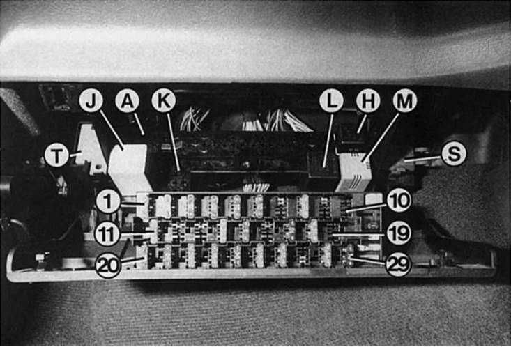
The fuse box on the passenger side looks different depending on equipment and version. After unscrewing the two screw locks on the left and right by a quarter of a turn, the fuse box can be lowered down.
If, when changing a fuse, you do not have a fuse of suitable capacity,
You can insert a stronger or weaker fuse for a while, but be sure to replace it with a fuse prescribed for this circuit as soon as possible.
The fuses can be replaced in the fuse box on the passenger side. You can also replace the relay there. You can access the relay box in the engine compartment by opening the hood.
1. In order to pull out the fuse, you must have thin pliers or tweezers.
2. If the new fuse blows immediately, see if you have inserted a fuse that is too weak.
3. If an appropriate fuse has been inserted, use the fuse table to determine which consumers are connected to this circuit and check them individually. The appropriate wiring diagram will also help you with this.
4. If in doubt, disconnect all consumers and reconnect them one by one. The consumer on which the fuse blows is faulty.