
Operating procedure:
- raise the front of the car and place supports under the body;
- remove the wheel from the desired side;
- remove the wheel caliper assembly from the brake disc as described above and tie it away from the work area without pulling the brake hose;
- mark the position of the brake disc on the hub in an accessible way;
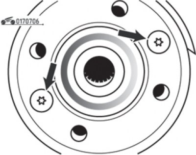
Pic. 7.6. Screws of fastening of a brake disk to a nave of a wheel (arrows)
- unscrew the two screws securing the disc to the hub using a T40 socket wrench (pic. 7.6) and remove the disc. If it is difficult to remove the disc, tap it with a rubber mallet;
- clean the disc from dirt and rust;
- check the brake disc. Measure the thickness of the disk with a micrometer in several places and compare it with the allowable one. If at least in one place the thickness of the disk is less than the permissible one, both disks must be replaced;
- slight scratches and grooves on the surfaces of the disc are allowed. In case of significant surface irregularities, it is possible to machine the disk on a lathe, making sure that the thickness of the disk does not go beyond the allowable limits;
- check the disc for cracks that may appear in the area of the wheel bolts. If cracks are found, replace both discs;
- clean the mating surfaces of the disc and hub;
- install the disk on the hub according to the marks made and tighten the mounting screws to the specified torque;
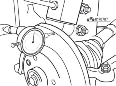
Pic. 7.7. Measuring brake disc runout with a dial gauge
- use a dial indicator to check disc runout over several radii (pic. 7.7). If the disc runout exceeds the allowable, you can try to move the disc 180°. Install the disc and check the runout again. If the runout is out of range, replace the disc;
- perform other operations in the reverse order of removal;
- at the end, press the brake pedal several times so that the pads approach the disc and take up their working position.