



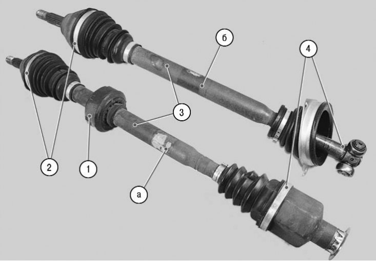
6.6. Front wheel drives: a - right front wheel drive; b – left front wheel drive; 1 – dynamic damper; 2 – external hinges; 3 – front wheel drive shafts; 4 – internal hinges
The front wheel drives consist of 2 outer (figure 6.6) and 4 internal constant velocity joints (CV joints) connected by shafts 3. The external joint enables only angular movements of the connected shafts. The internal joint, in addition to angular movements, also enables axial displacements of the shafts when turning the front wheels and operating the suspension. All joints of both drives are of the "Tripod" type, with the external joints of both drives being identical in design, and the internal ones being different. Therefore, the right and left drives are not interchangeable. To reduce vibration in the transmission, a dynamic damper 1 is installed with tension on the shaft of the right drive.
The Renault Logan uses external joints of the GE 86 type and internal joints of the GL 69 (left) and RC 462 (right) type.
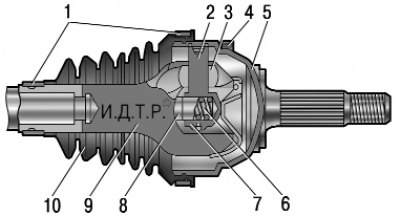
6.7. GE 86 Outer Constant Velocity Joint: 1 – cover fastening clamps; 2 – three-spike hub; 3 – roller; 4 – ABS sensor toothed disk (with ABS); 5 – hinge body; 6 – spring; 7 – adjusting spacer; 8 – pusher; 9 – drive shaft; 10 – hinge cover
The outer hinge 2 consists of a housing 5 (figure 6.7) and three rollers 3, put on the journals of the three-spike hub 2. The latter is made in one piece with the hinge housing. The rollers enter the grooves of the hinge cage, made in one piece with the drive shaft 9. This design allows the hinge to rotate at the required angle. The splined tail of the outer hinge housing is secured in the front wheel hub with a nut. The hinge is sealed with a cover 10, secured with clamps 1 on the hinge housing and on the drive shaft.
To repair the outer joint, only its cover and cover fastening clamps are supplied as spare parts. In case of failure, the joint must be replaced together with the drive shaft, since the joint cage forms a non-separable unit with the shaft.
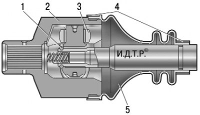
6.8. Right inner constant velocity joint RC 462: 1 – retaining ring; 2 – hinge housing; 3 – three-spike hub roller; 4 – cover fastening clamps; 5 – hinge cover; 6 – spring
The right inner hinge consists of housing 2 (figure 6.8) and three rollers 3 on needle bearings mounted on the journals of the three-spike hub. Grooves for the rollers are made in the hinge housing. The three-spike hub is fixed on the drive shaft with a retaining ring 1, the rollers allow the hub to move in the grooves of the hinge housing in the axial direction, due to which the drive can be lengthened or shortened to compensate for the mutual movements of the suspension and the power unit. The tip of the inner hinge housing with internal splines is mounted on the splined shank of the right half-axle gear. From axial movement on the shank of the gear during suspension operation, the hinge housing is fixed by an expansion spring 6 installed inside the hinge. The hinge is sealed by a cover 5, secured with clamps 4 on the hinge housing and on the drive shaft. In the gearbox housing, the tip of the hinge housing is sealed with a toroidal rubber ring and a self-tightening oil seal.
To repair the right inner joint, two repair kits are supplied in the spare parts section: a large one, which includes all the joint parts, and a small one, similar to the repair kit for the outer joint.
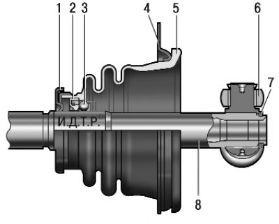
6.9. Left inner constant velocity joint GL 69: 1 – mud deflector; 2 – oil seal; 3 – bearing; 4 – case holder; 5 – hinge cover; 6 – three-spike hub roller; 7 – retaining ring; 8 – drive shaft
The left inner joint consists of three rollers 6 (figure 6.9) on needle bearings mounted on the journals of a three-pin hub. The function of the hinge housing is performed by the left half-axle gear of the gearbox of complex shape. Its internal grooves for the rollers are made similar to the grooves of the housing 2 (see figure 6.8) right inner joint. The three-pin hub is fixed on shaft 8 (see figure 6.9) drive by means of a retaining ring 7. The rollers allow the hub to move in the grooves of the axle gear in the axial direction, due to which the drive can be lengthened or shortened to compensate for the mutual movements of the suspension and the power unit. The joint is sealed by means of a cover 5, fixedly secured with the help of a holder 4 on the gearbox housing. The drive shaft, rotating inside the cover in bearing 3, is sealed by means of a seal 2, installed under the cover in a removable unit, common with the bearing.
To repair the left inner joint, two repair kits are supplied in the spare parts section: a large one, which includes all the joint parts except the axle gear, and a small one, which includes the joint cover and the bearing assembly with the seal.
To lubricate the outer joints and the right inner joint, use a special lubricant with molybdenum disulfide MOBIL CVJ 825 BLACK STAR (supplied with the joint repair kit, the domestic analogue is SHRUS-4). The splines of the inner joint tailpiece are lubricated with MOLYKOTE BR2 consistent grease, and the left inner joint is lubricated with transmission oil for the gearbox.
Note. Drive joints are very durable, their estimated service life is almost equal to the service life of the car. However, they are often replaced or repaired during operation due to the fact that no attention is paid to the condition of the protective covers. Such work is quite expensive and labor-intensive. In order to save a lot, regularly check the condition of the protective covers of the joints and replace them immediately at the slightest damage. If water or dust gets into the joint through a damaged cover, it will fail after several hundred kilometers. A sealed joint wears out extremely slowly.