



Contents: Removal 🠛 Installation 🠛
Note: This chapter describes the removal of the transmission without the engine, which remains in the vehicle. If you have a sufficiently powerful lifting mechanism at hand, it is recommended to remove the power unit assembly (it's much easier) as described in Section 2F, and then separate them on the workbench. Where present (see text), new right-hand drive shaft to differential axle pinion retaining pins and suitable sealant will be required during installation.
Removal
1. The gearbox is removed from the engine compartment upwards. The block is heavy and suitable lifting equipment is required.
2. Apply the handbrake, then jack up the front of the car and place it on axle stands. Remove both front wheels.
3. Remove the battery (see Section 5A).
4. Remove the hood (Section 11).
5. Remove the plastic cover from the base of the gearbox. Place a suitable container under the transmission, then remove the drain plug and allow the oil to drain (see illustration).
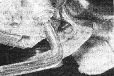
7.5. Remove the transmission drain plug.
Once all the oil has drained, clean and install the drain plug, tightening it securely.
View the original source on this resource RENAULTBOOK.ru
6. Unscrew the nut securing the left tie rod end to the steering arm, then use a special puller to separate the ball joint pin from the arm.
7. Working in the engine compartment, remove the three bolts securing the inner rubber boot of the left drive shaft to the gearbox.
8. Remove the left brake caliper from the steering knuckle (see Section 9). Do not disconnect the brake hose from the caliper. Tie the caliper to the suspension spring, being careful not to stretch the hose.
9. Remove the pinch bolt securing the front lower ball joint to the base of the left steering knuckle.
10. Support the steering knuckle and drive shaft with a jack, then remove the two bolts and separate the steering knuckle from the base of the suspension strut.
11. Remove the left drive shaft (complete with steering knuckle) from the gearbox. Make sure the CV joint tripod components remain in the operating position on the inner end of the drive shaft, otherwise they may fall into the transmission.
12. On the right drive shaft, push out the cylindrical pins (where available) using a 5 mm diameter punch.
Note: On some late models the roll pins on the inner end of the drive shaft are not used - ignore references to removing and installing the pins on such vehicles.
13. Loosen up (but don't take it off) lower bolt securing the right steering knuckle to the base of the suspension strut. Loosen and remove the top bolt, then tilt the steering knuckle and disconnect the drive shaft from the differential axle pinion shaft.
14. Cut the plastic tie and slide the rubber boot back, then disconnect the gear shift rod from the lever on the transmission by unscrewing the nut and removing the bolt (see illustrations).
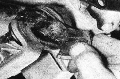
7.14a. Slide the rubber boot...
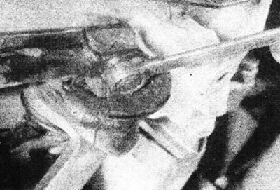
7.14b.... then disconnect the shift rod from the lever on the transmission.
Remove the bushing from the lever. Do not separate the shift rod from the clamp, otherwise you will have to adjust the position of the lever during installation.
15. Remove the protective cover of the inner panel of the front left wing (where necessary, drill out rivets).
16. On C-series engines, loosen and remove the cover from the base of the clutch housing.
17. On E-series engines, loosen the powertrain tie rod bracket mounting bolts and remove the bracket (see illustrations).
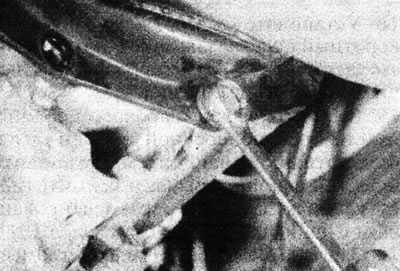
7.17a. Remove the powertrain tie rod bracket bolts from the gearbox...
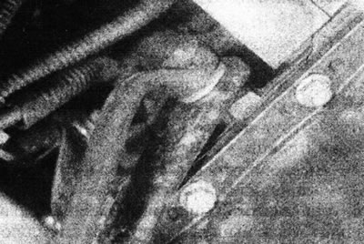
7.17b.... and from the engine - E series engines.
18. On all engines, remove the transmission-to-engine mounting nut located near the right drive shaft.
19. Pull out the clamp and disconnect the speedometer drive cable from the transmission (near the rear suspension).
20. Disconnect the clutch cable from the gearbox (see Section 6).
21. Disconnect the ground strap from the transmission housing.
22. Disconnect the wiring harness connector from the reverse light switch on the transmission housing.
C series engines
23. Unfasten and remove the power unit tie rod.
E series engines
24. Loosen up (but don't take it off) bolt A, then unscrew and remove bolt B of the rear suspension support bar (see illustration).
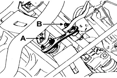
7.24. Rear Engine/Transmission Mounting Bar - E Series Engines: A - Rear mounting bolt; B - Front mounting bolt.
25. Drain the cooling system (see Section 1).
26. Loosen the clamps and remove the upper radiator hose. Also remove the thermostat.
27. Remove the distributor cap (see section 5B or 5C).
28. Where present, remove the engine speed sensor (flywheel) and ignition module (Section 4B or 4C).
29. Loosen up (but don't take it off) the bolt securing the rear suspension bracket to the gearbox and rotate the suspension downwards.
All engines
30. Remove pin A (see illustration) using a nut and lock nut.
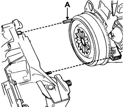
7.30. Gearbox mounting stud (A) on the engine.
31. Attach a suitable winch to the engine and lift it slightly. Alternatively, support the engine with a jack and use a winch to remove the transmission.
32. Remove the right engine/battery mount mounting bracket along with its gasket (if any).
C series engines
33. Remove the air cleaner housing assembly (see Section 4A).
34. Remove the nut securing the front transmission bracket to the engine subframe. Remove the front bracket from the gearbox.
35. Unfasten and remove the rear suspension from the transmission.
36. Note the correct location of the wiring harness going to the engine, then disconnect it and remove it from the transmission.
All engines
37. Loosen and remove the nuts and bolts securing the engine to the transmission. There is no need to remove the starter.
38. Support the weight of the transmission with a jack. Separate the transmission from the engine by sliding its rear cover between the engine subframe and the front fender side panel. To remove the clutch housing from the engine mounting pins, carefully use a wide screwdriver. Do not allow the gearbox to hang on the input shaft.
39. Turn the transmission forward to engage the final drive. Lift the gearbox out of the engine compartment with the clutch housing facing up. If using a winch, attach it to the clutch housing mounting bolt holes.
Installation
40. Perform installation in reverse order, paying attention to the following:
- Before installing the transmission onto the engine, place a piece of wood or similar spacer between the end of the clutch release fork and the cable housing bracket on the transmission case to hold the fork in the released position. This will prevent the release bearing from slipping off the end of the clutch release fork during installation.
- Make sure all mounting pins are in the working position.
- Apply a small amount of high temperature grease to the gearbox input shaft grooves. Measure the amount of grease very carefully, otherwise it may contaminate the clutch friction disc.
- Make sure the starter centering sleeve is installed correctly. See Section 5A, if necessary.
- Where present, use new roll pins when installing the right-hand drive shaft and apply a suitable sealant to the ends of the roll pins.
- Install and tighten the brake caliper mounting bolts (see Section 9).
- Where necessary, check the engine mount adjustment dimensions (see Section 2).
- Fill the gearbox with oil and check its level as described in Section 1.
- Tighten all nuts and bolts to the specified torque Specifications.
- Fill the cooling system (see Section 1).