



Contents: Throttle body 🠛 Inlet air temperature sensor 🠛 Coolant temperature sensor 🠛 Fuel injectors 🠛 Idle speed control valve 🠛 Fuel pressure regulator 🠛 Throttle potentiometer 🠛 Throttle Body Heater - F7P Engines…🠛 Intake manifold pressure sensor 🠛 Motion speed sensor 🠛 Engine speed sensor (flywheel) 🠛 Processor unit 🠛 Inertia fuel supply switch 🠛
Note: Please read the procedure description carefully before proceeding. Also see warning at the end Chapters 1.
Throttle body
D-series engine
Note: The intake air temperature sensor, idle speed control valve and throttle potentiometer are mounted in the throttle body and cannot be replaced separately. A new seal will be required during installation.
1. Disconnect the negative cable from the battery.
2. Loosen the clamps and remove the air ducts connecting the air filter assembly to the throttle body.
3. Disconnect the wiring from the idle speed control valve, air temperature sensor and throttle position sensor (see illustrations).
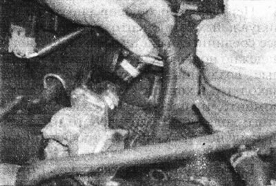
15.3a. Disconnect the wiring from the idle speed control valve...
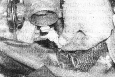
15.3b....air temperature sensor...
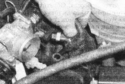
15.3 sec....and throttle position sensor - D-series engine.
4. Disconnect the accelerator pedal cable from the throttle lever, if necessary see Chapter 3 (see illustration).
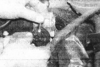
15.4 Disconnect the accelerator pedal cable from the throttle lever - D-series engine.
5. Unscrew the three throttle body mounting bolts (see illustration).
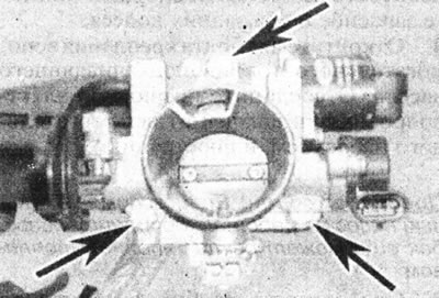
15.5. Throttle body mounting bolts (marked with arrows) - D-series engine.
6. Remove the two bolts securing the bracket to the cylinder head or the bolts securing the support bracket to the throttle body bracket, then remove the throttle body together with the brackets. Remove the seal (see illustrations).
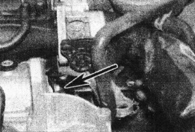
15.6a. Bolt for fastening the throttle body support bracket to the cylinder head (marked with an arrow) - D-series engine.
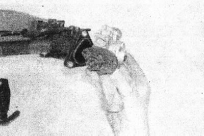
15.6b. Remove the throttle body...
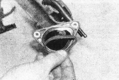
15.6 sec....and remove the seal - D-series engine.
7. Install in reverse order, use a new seal, connect and adjust the accelerator pedal cable.
F3P engines
Note: A new gasket will be required during installation.
8. Disconnect the negative cable from the battery.
9. Disconnect the air temperature sensor wiring, loosen the clamps securing the intake air duct, then loosen the screw securing the air duct pipe to the engine. Disconnect the breather hose from the top of the duct, then disconnect the duct from the throttle body and pipe, disconnect the remaining two breather hoses, and remove the duct (see illustrations).
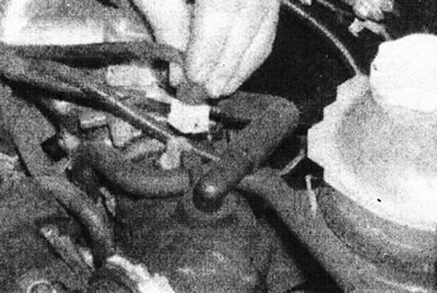
15.9a. Disconnect the air temperature sensor wiring...
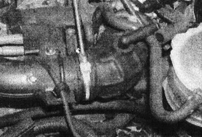
15.9b....loose the clamps securing the intake air duct...
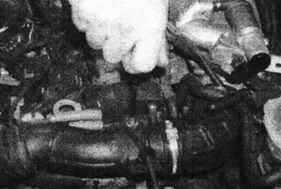
15.9s....and loosen the screw securing the air duct pipe to the engine.
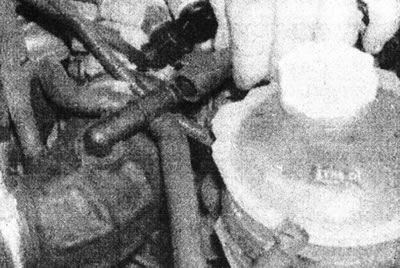
15.9d. Disconnect the breather hose from the top of the air duct.
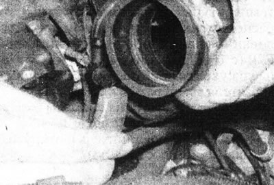
15.9e. Disconnect the remaining hoses and remove the air duct.
10. Disconnect the throttle position sensor wiring. Trace the wiring from the throttle position sensor and disconnect the connector.
11. Disconnect the accelerator pedal cable from the throttle lever, if necessary see Chapter 3.
12. Remove the four mounting bolts, then remove the throttle body from the intake manifold and remove the gasket (see illustrations).
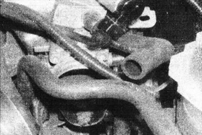
15.12a. Unscrew the top...
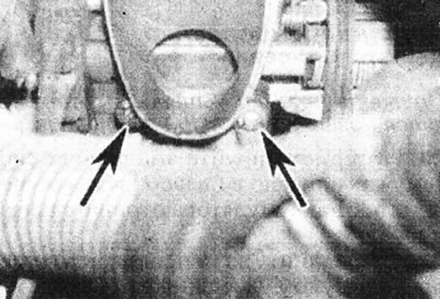
15.12b....and the lower throttle body mounting bolts - F3P engine.
13. Install in reverse order, using a new gasket.
R7R engines (with 16 valves)
14. Disconnect the negative cable from the battery.
15. Disconnect the accelerator pedal cable, electrical wiring and hoses from the throttle body.
16. Separate the air filter housing from the throttle body.
17. Unscrew the throttle body from the intake manifold and remove it.
18. Install in reverse order.
Inlet air temperature sensor
Removal
19. On D-series engines, the intake air temperature sensor is mounted in the throttle body and is not accessible separately. If the sensor is faulty, the throttle body must be replaced. On F3P engines, the sensor is located in the air duct connecting the throttle body to the air cleaner housing. On F7P engines (with 16 valves), the sensor is located at the right end of the intake manifold.
20. Disconnect the sensor wiring (see illustration).
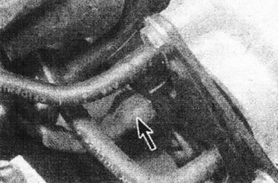
15.20. Inlet air temperature sensor wiring connector (marked with an arrow) - F7P engine (with 16 valves).
21. On F7P engines (with 16 valves), unscrew and remove the sensor. On F3P engines, carefully remove the sensor from the air duct.
Installation
22. Install in reverse order.
Coolant temperature sensor
Removal
23. On D-series and F3P engines, the coolant temperature sensor is located at the front left end of the cylinder head. On F7P engines (with 16 valves), the sensor is located on the thermostat housing, next to the temperature gauge sensor.
24. Drain the cooling system as described in Section 1.
25. Disconnect the connector and unscrew the sensor (see illustration).
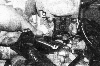
15.25. Disconnect the coolant temperature sensor wiring - D-series engine.
Installation
26. Apply a small amount of sealant to the sensor threads and screw it into place. Connect the electrical wiring.
27. Fill the cooling system.
Fuel injectors
D-series engine
Note: New O-rings will be required during installation.
28. Depressurize the fuel system as described in Chapter 7, then disconnect the negative cable from the battery.
29. Disconnect the fuel injector wiring harness. The connector is located in front of the fuel pressure regulator (see illustration).
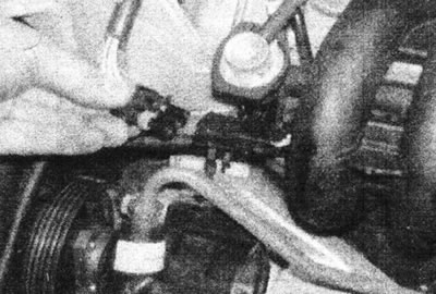
15.29. Disconnect the fuel injection system wiring - D-series engine.
30. Disconnect the vacuum line from the fuel pressure regulator (see illustration).
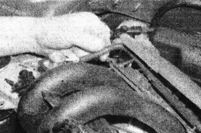
15.30 Disconnect the vacuum line from the fuel pressure regulator - D-series engine.
31. Disconnect the fuel return pipe from the fuel line (see illustration).
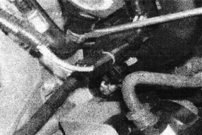
15.31 Loosen the clamp, then disconnect the return line from the fuel line - D-series engine.
Plug the hose to prevent dirt from entering and fuel loss.
32. Now you need to disconnect the supply hose from the fuel line. This will require a special Renault tool (Mot. 1311-06) (see illustrations).
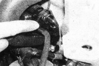
15.32a. Push the retainer and release the expansion tabs of the fuel supply hose connector...
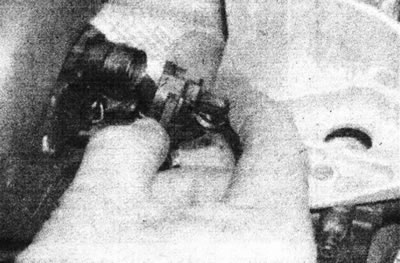
15.32b....then disconnect the hose from the fuel line.
Plug the hose to prevent dirt from entering and fuel loss.
33. Working under the manifold, unscrew the two bolts securing the fuel line to the manifold (see illustration).
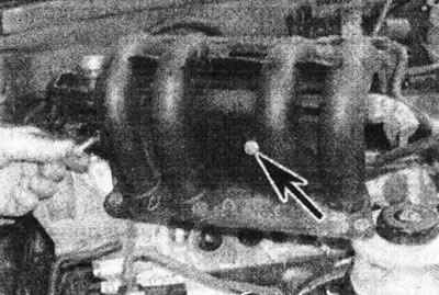
15.33. Loosen the fuel line mounting bolts (marked with an arrow).
34. Carefully slide the fuel rail and injector assembly toward the right side of the vehicle, between the manifold and the cylinder head.
35. To remove the injector from the fuel line, fold back the wiring harness clips and separate the wiring harness assembly from the top of the injectors. Remove the retaining bracket and remove the fuel injector (see illustrations).
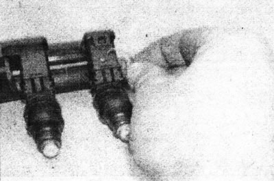
15.35a. Release the injector wiring harness retaining clip...
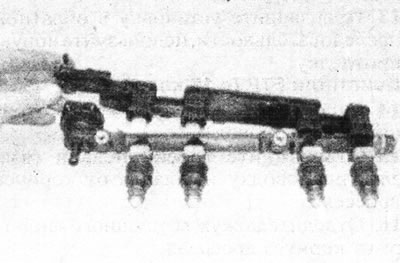
15.35b....and separate the assembly from the top of the injectors - D-series engine.
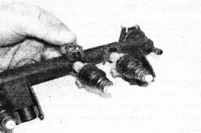
15.35 sec. Remove the mounting bracket...
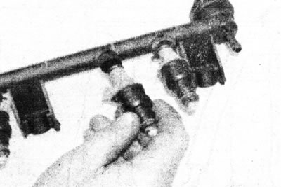
15.35d....and remove the fuel injector - D-series engine.
36. Install in reverse order, replace the O-rings on each injector, and make sure the fuel supply hose is securely connected (the connector should snap into place).
F3P engines
Note: Installation will require new injector O-rings and new fuel rail to cylinder head seals.
37. Depressurize the fuel system, see Chapter 7, then disconnect the negative cable from the battery.
38. Loosen the clamps and disconnect the supply and return hoses from the fuel line (see illustration).
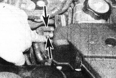
15.38. Disconnect the supply and return hoses from the fuel line (marked with arrows) - F3P engine.
Mark their location so as not to get confused when connecting. Cap the open ends of the hoses.
39. Disconnect the vacuum line from the fuel pressure regulator.
40. Disconnect the connectors from the intake air temperature sensor and the idle speed control valve.
41. Release the connector of the wiring harness going to the engine from the bracket next to the expansion tank, then disconnect the wiring (see illustration).
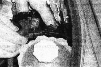
15.41. Release the wiring harness connector going to the engine from the bracket and disconnect it - F3P engine.
Release the wiring harness from the brackets above the fuel injectors and move it to the side.
42. Disconnect the electrical wiring from the fuel injectors (see illustration).
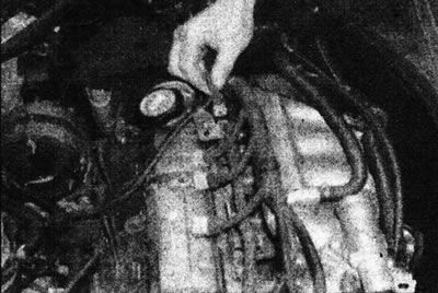
15.42. Disconnect the electrical wiring from the fuel injectors - F3P engine.
43. Release the breather hose and wire harnesses from the clamps on the fuel line and move them away from the fuel line.
44. Unscrew the two screws and remove the fuel injector clamp for cylinder #3.
45. Unscrew the two fuel line mounting nuts, then remove the line and injector assembly (see illustration).
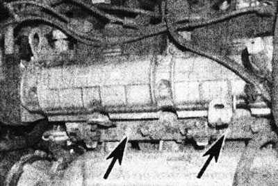
15.45. Fuel line fastening nuts (marked with arrows) - F3P engine.
Remove the four seals from the base of the fuel line.
46. To remove the injector from the fuel line, unscrew the two screws and remove the clamping bar, then pull out the injector.
47. Perform installation in reverse order, paying attention to the following:
- Replace the injector O-rings.
- Use new seals between the fuel line and the cylinder head.
- Make sure the supply and return hoses are properly connected as noted before removal.
F7P engines (with 16 valves)
Note: New injector O-rings will be required during installation.
48. Depressurize the fuel system as described in Chapter 7, then disconnect the negative cable from the battery.
49. Remove the cover from the top of the intake manifold.
50. Disconnect the supply and return hoses from the fuel line.
51. Remove the breather hoses and tubes that run from the valve cover to the fuel line. Also disconnect the vacuum hose from the fuel pressure regulator.
52. Disconnect the electrical wiring from the injectors (see illustration).
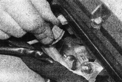
15.52. Disconnect the electrical wiring from the fuel injectors - F7P engine (with 16 valves).
53. Unscrew the mounting nut and remove the fuel line and injectors (see illustration).
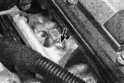
15.53. The fuel line is secured with one nut (marked with an arrow) - F7P engine (with 16 valves).
54. The injectors can be separated from the line by removing the corresponding fasteners.
55. Install in reverse order. Use new injector O-rings. Apply a small amount of silicone grease to the O-rings.
56. Check that there are no fuel leaks.
Cold start injector - early F7P engines (with 16 valves)
57. Disconnect the negative cable from the battery.
58. Remove the hood and hood hinge crossmember as described in Section 11.
59. Tilt the radiator forward. Disconnect the crankcase ventilation hose from the intake manifold and unscrew the support strut.
60. Disconnect the fuel coupling from the cold start injector (see illustration).
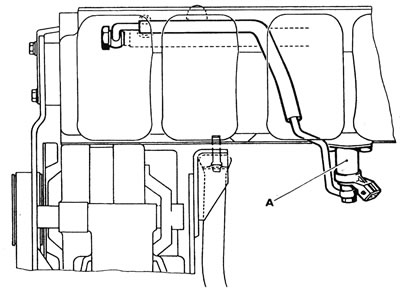
15.60. Location of cold start injector (A) on intake manifold - F7P engine (with 16 valves).
61. Unscrew the two mounting screws and remove the injector from the manifold.
62. Install in reverse order. Before installing the hood hinge crossbar, connect the battery and turn on the fuel pump by short-circuiting the corresponding relay contacts with a jumper (see Chapter 9). Check that there are no fuel leaks around the coupling on the injector.
Idle speed control valve
F-series engine
63. The idle speed control valve is mounted in the throttle body and cannot be replaced separately. If the valve is defective, replace the throttle body.
F3P engines
Note: A new gasket will be required during installation.
64. Disconnect the negative cable from the battery.
65. Disconnect the control valve wiring (see illustration).
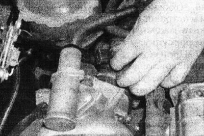
15.65. Disconnect the idle speed control valve wiring - F3P engine.
66. Unscrew the two mounting screws and remove the valve from the intake manifold (see illustration).
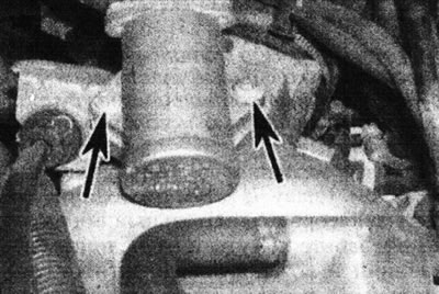
15.66. Idle speed control valve mounting screws (marked with arrows) - F3P engine.
Remove the gasket.
67. Install in reverse order, using a new gasket.
F7P engines (with 16 valves)
68. Disconnect the negative cable from the battery.
69. Disconnect the connector from the top of the valve (see illustration).
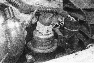
15.69. Idle speed control valve wiring connector (marked with an arrow) - F7P engine (with 16 valves).
70. Remove the valve mounting clamp. Disconnect the hoses and remove the valve.
71. Install in reverse order.
Fuel pressure regulator
D-series engine
Note: New O-rings will be required during installation.
72. Depressurize the fuel system, see Chapter 7, then disconnect the negative cable from the battery.
73. Disconnect the vacuum hose from the pressure regulator.
74. Remove the mounting bracket, then carefully remove the pressure regulator from the casing. Mark the location of the vacuum hose connection so that the regulator can be installed in the correct position. Remove the O-rings (see illustrations).
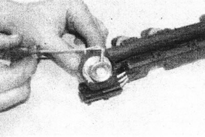
15.74a. Using a screwdriver...
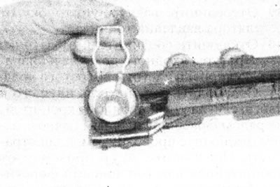
15.74b....release the mounting bracket...
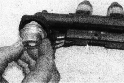
15.74s....then remove the fuel pressure regulator from the housing - D-series engine.
75. Install in reverse order, use new O-rings and ensure that the retaining ring is seated correctly in the groove (see illustrations).
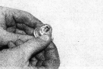
15.75a. Replace the top...
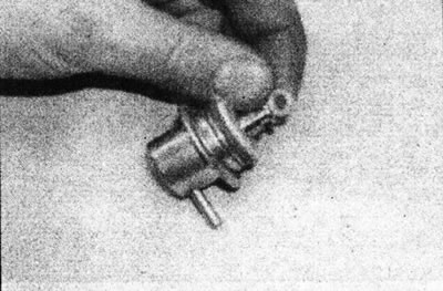
15.75b....and lower fuel pressure regulator o-rings - D-series engine.
F3P engines
Note: New O-rings will be required during installation.
76. Depressurize the fuel system as described in Chapter 7, then disconnect the negative cable from the battery.
77. Remove the fuel line and injectors as described earlier in this Chapter.
78. Unscrew the two mounting screws and remove the pressure regulator clamping plate.
79. Carefully remove the pressure regulator from the fuel line. Remove the O-rings.
80. Perform installation in reverse order, use new O-rings, and install the fuel line and injectors as described earlier in this Chapter.
F7P engines (with 16 valves)
81. Depressurize the fuel system as described in Chapter 7, then disconnect the negative cable from the battery.
82. Remove the cover from the top of the intake manifold. Disconnect the vacuum hose from the fuel pressure regulator and remove the two mounting screws (see illustration).
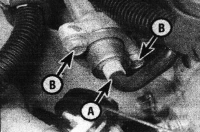
15.82. Fuel pressure regulator vacuum hose (A) and mounting screws (B) - F7P engine (with 16 valves).
83. Remove the fuel pressure regulator from the fuel line.
84. Install in reverse order. Finally, check for any fuel leaks.
Throttle potentiometer
D-series engine
85. The throttle potentiometer is mounted in the throttle body and cannot be replaced separately. If the valve is faulty, replace the throttle body.
F3P engines
Note: If a new potentiometer is installed, it is necessary to check its original position using a special Renault XR25 tester.
86. Remove the throttle body as described earlier in this Chapter.
87. Loosen the two mounting screws and remove the throttle potentiometer from the throttle body.
88. Install in reverse order, making sure the throttle shaft is properly engaged with the potentiometer arm and the potentiometer should be facing the electrical connector towards the intake air duct. If a new potentiometer is installed, it is necessary to check its original position using the Renault XR25 tester.
F7P engines (with 16 valves)
Note: If a new potentiometer is installed, it is necessary to check its original position using a special Renault XR25 tester.
89. Make alignment marks on the potentiometer and the throttle body.
90. Disconnect the wiring, then unscrew the two screws and remove the potentiometer (see illustration).
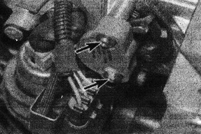
15.90. Throttle potentiometer mounting screws (marked with arrows) - F7P engine (with 16 valves).
91. Install in reverse order. If a new potentiometer is installed, it is necessary to check the initial position of the potentiometer using the Renault XR25 tester.
Throttle Body Heater - F7P Engines (with 16 valves)
92. Disconnect the negative cable from the battery. Remove the two screws and the heater from the throttle body (see illustration).
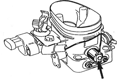
15.92. Heater (marked with an arrow) on the back side of the throttle body - F7P engine (with 16 valves).
93. Install in reverse order.
Intake manifold pressure sensor
D-series engine
94. The sensor is fixed inside the air filter housing.
95. Disconnect the electrical wiring from the sensor, then disconnect the sensor vacuum hose from the intake manifold (see illustrations).
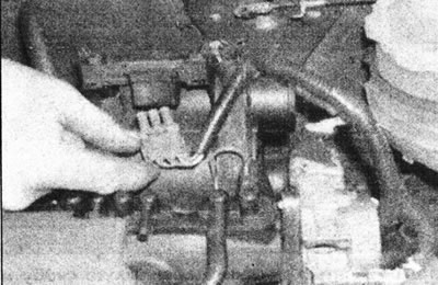
15.95a. Disconnect the wiring from the intake manifold pressure sensor - D-series engine.
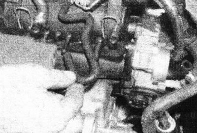
15.95b. Disconnect the pressure sensor vacuum hose from the intake manifold - D-series engine.
96. Carefully release the two mounting brackets and remove the sensor from the air filter housing.
97. Install in reverse order.
F3P and F7P engines (with 16 valves)
98. Proceed as described in Parts B, Chapter 14 of this Section.
Motion speed sensor
99. The speed sensor is mounted in the speedometer drive cable (see illustration).
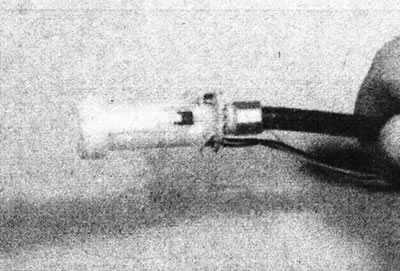
15.99. The speed sensor is built into the speedometer drive cable.
For cable replacement procedure, see. in Section 12.
Engine speed sensor (flywheel)
100. Proceed as described in Parts B, Chapter 14 of this Section.
Processor unit
D-series engine
101. Remove the battery as described in Section 5A.
102. Remove the bolt securing the processor mounting plate and shield to the battery bracket and the two nuts securing the processor mounting plate to the body and remove the processor unit with the shield (see illustrations).
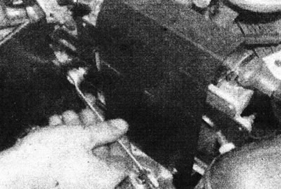
15.102a. Remove the screw securing the processor unit mounting plate - D-series engines.
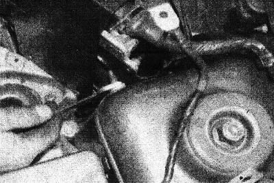
15.102b. Remove one of the nuts securing the processor unit mounting board to the body - D-series engines.
103. Carefully slide the shield off the block (see illustration).
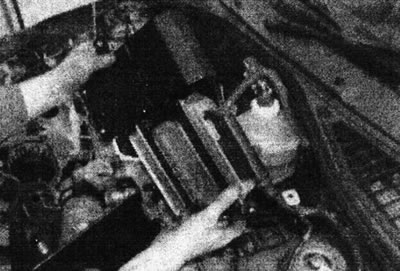
15.103. Slide the shield off the processor unit...
104. Fold back the retaining clip and disconnect the electrical wiring connector from the processor unit, then remove the unit from the engine compartment (see illustration).
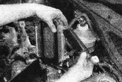
15.104. ...then fold back the mounting bracket and disconnect the electrical wiring - D-series engine.
105. Install in reverse order.
F3P and F7P engines (with 16 valves)
106. Proceed as described in Parts B, Chapter 14 of this Section.
Inertia fuel supply switch
107. Proceed as described in Parts B, Chapter 14 of this Section.