



D-series engine
Note: New rubber seals will be required during installation.
Removal
1. Depressurize the fuel system as described in Chapter 7, then disconnect the negative cable from the battery.
2. Loosen the clamps and remove the air duct connecting the air cleaner assembly to the throttle body (see illustration).
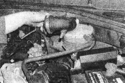
17.2 Remove the air duct connecting the air cleaner assembly to the throttle body - D-series engine.
3. Disconnect the high tension wires from the spark plugs.
4. Release the top of the high tension wire housing, then move the wires away from the intake manifold.
5. Disconnect the fuel hoses from the charcoal canister solenoid valve (see illustration).
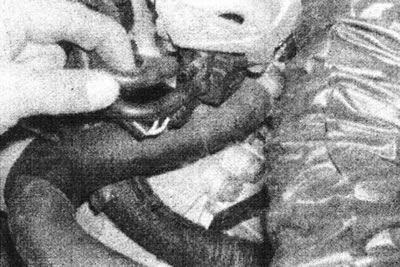
17.5 Disconnect the fuel hoses from the charcoal canister solenoid valve - D-series engine.
6. Disconnect the valve cover breather hose from the intake manifold (see illustration).
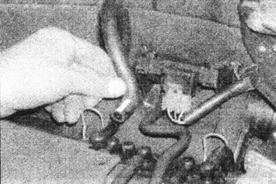
17.6 Disconnect the valve cover breather hose from the intake manifold - D-series engine.
7. Disconnect the brake booster vacuum hose and the manifold pressure sensor vacuum hose from the intake manifold (see illustration).
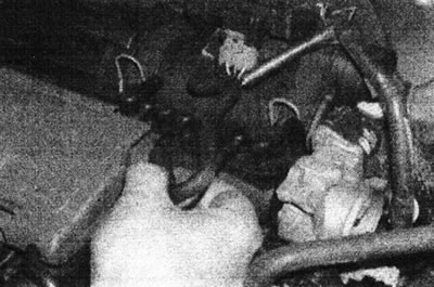
17.7 Disconnect the pressure sensor hose from the intake manifold - D-series engine.
8. Disconnect the supply and return hoses from the fuel line. To disconnect the fuel supply hose, you will need a special Renault tool (Mot. 1311-06) (see illustrations 15.31, 15.32a and 15.32b).
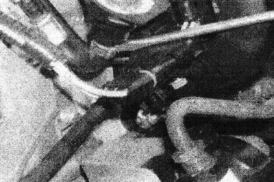
15.31 Loosen the clamp, then disconnect the return line from the fuel line - D-series engine.
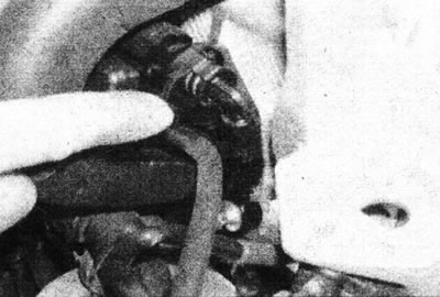
15.32a. Push the retainer and release the expansion tabs of the fuel supply hose connector...
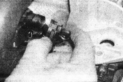
15.32b....then disconnect the hose from the fuel line.
9. Disconnect the electrical wiring from the following components (see illustration):
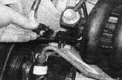
17.9 Disconnect the fuel injector wiring harness - D-series engine.
- Idle speed control valve.
- Throttle position sensor.
- Air temperature sensor.
- Fuel injector wiring harness.
10. Disconnect the gas pedal cable from the throttle lever (see illustration).
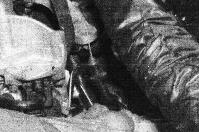
17.10. Disconnect the accelerator pedal cable - D-series engine.
11. Release the engine oil level dipstick from the bracket on the intake manifold, then remove the dipstick from the pipe (see illustration).
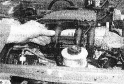
11/17 Remove the oil dipstick - D-series engine.
12. Unscrew the six nuts securing the manifold to the cylinder head (see illustration).
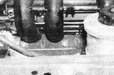
12/17. Two of the intake manifold to cylinder head mounting nuts - D-series engine.
13. Remove the two bolts securing the manifold to the top of the cylinder head, one of the bolts goes through the spark plug wire cover (see illustrations).
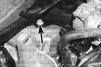
17.13a. Remove the two bolts securing the intake manifold to the top of the cylinder head...
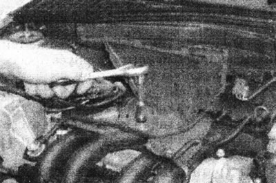
17.13b....one of the bolts goes through the spark plug wire housing - D-series engine.
14. Remove the two bolts securing the support bracket to the throttle body (see illustration).
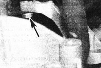
17.14. Bolt for fastening the support bracket to the throttle body (marked with an arrow) - D-series engine.
15. Disconnect the charcoal canister hose from the fitting on the right side of the manifold (see illustration).
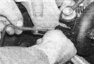
17.15. Disconnect the carbon canister hose from the D-series engine connection.
16. Carefully remove the manifold from the cylinder head. Remove the rubber seals (see illustration).
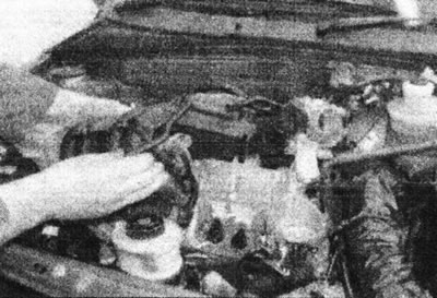
17.16. Separate the manifold from the cylinder head...
17. Rotate the manifold to access the two fuel line mounting bolts.
18. Remove the fuel line mounting bolts, disconnect the vacuum hose from the fuel pressure regulator, then remove the injector/fuel line assembly (see illustrations).
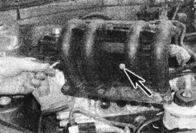
17.18a....then turn the manifold and unscrew the fuel line mounting bolts - D-series engine.
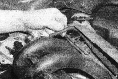
17.18b. Disconnect the vacuum hose from the fuel pressure regulator...
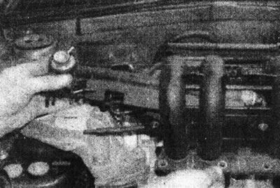
17.18s....then remove the fuel line - D-series engine.
19. Disconnect the fuel supply hose from the fuel line and move it to the side, then remove the manifold (see illustration).
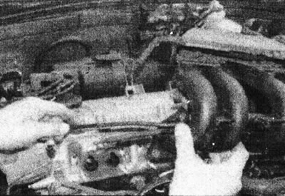
17.19 Disconnect the fuel supply hose, then remove the manifold - D-series engine.
Installation
20. Install in reverse order, paying attention to the following:
- Use new rubber seals.
- Connect and adjust the gas pedal cable (see Chapter 3).
- Make sure the fuel supply hose is securely connected (the connector should snap into place).
- Check that each hose is connected to its own outlet.
F3P engines
Note: Installation will require a new manifold gasket and a new gasket between the outlet pipe and manifold.
Removal
21. Depressurize the fuel system as described in Chapter 7, then disconnect the negative cable from the battery.
22. Loosen the clamps and disconnect the feed and return hoses from the fuel line.
23. Disconnect the brake booster vacuum hose from the intake manifold (see illustration).
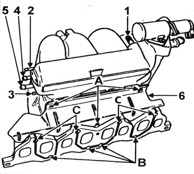
17.23. Intake Manifold Connections - F3P Engine: 1 - Brake booster vacuum hose; 2 - Pressure sensor hose; 3 - Fuel pressure regulator hose; 4 - Carbon canister hose; 5 - Breather hose; 6 - Collector heat-insulating shield; A - Bolts for fastening the heat-insulating shield; B - Lower manifold mounting nuts; C - Upper manifold mounting studs.
24. Disconnect the vacuum hose from the fuel pressure regulator.
25. Disconnect the intake manifold pressure sensor vacuum hose, fuel vapor recirculation hose, and engine breather hose from the right end of the manifold.
26. Disconnect the connectors from the air temperature sensor, idle speed control valve, and throttle potentiometer.
27. Loosen the clamps and remove the intake air duct connecting the air cleaner assembly to the throttle body.
28. Remove the fuel injector and fuel rail assembly as described in Chapter 15.
29. Remove the hose bracket from the top of the intake manifold.
30. Release the remaining wiring from the brackets and clamps on the intake manifold.
31. Remove the throttle body (see Chapter 15).
32. Remove the three nuts securing the throttle body heat shield to the exhaust manifold.
33. Working under the vehicle, disconnect the oxygen sensor wiring.
34. Unscrew the mounting nuts and disconnect the outlet pipe from the manifold. Remove the gasket.
35. Unscrew and remove the left exhaust manifold/outlet pipe bracket stand, then remove the throttle body heat shield.
36. Unscrew the three mounting bolts and remove the heat-insulating shield.
37. Loosen the four center lower manifold nuts a few turns.
38. Remove the four upper manifold nuts, then remove the upper mounting studs (see illustration 17.23).
39. Carefully separate the intake manifold, then remove it from the engine compartment.
40. Unscrew and remove the six lower mounting nuts (the central four were already weakened), then remove the exhaust manifold.
41. Remove the gasket.
Installation
42. Perform installation in reverse order, paying attention to the following:
- Use new gaskets.
- Install the throttle body and injector/fuel line assembly as described in Chapter 15.
- Properly connect and route all wires and hoses as noted prior to removal.
F7P engines (with 16 valves)
Note: A new manifold gasket will be required during installation.
Removal
43. Remove the radiator as described in Section 3.
44. Remove the main fuel injectors and cold start injector as described in Chapter 15.
45. Remove the air filter as described in Chapter 2.
46. Remove the generator as described in Section 5A, and unscrew the bolts securing the generator bracket to the manifold.
47. Disconnect the remaining hoses and wiring from the manifold. Unscrew the manifold studs, unscrew the nuts and remove the manifold.
Installation
48. Install in reverse order, using a new gasket.