



Contents: Air intake casing (f3P engine only) 🠛 Throttle body 🠛 Inlet air temperature sensor 🠛 Coolant temperature sensor 🠛 Fuel injector 🠛 Idle speed drive motor 🠛 Fuel pressure regulator 🠛 Throttle potentiometer 🠛 Intake manifold pressure sensor 🠛 Motion speed sensor 🠛 Intake manifold heater 🠛 Engine speed sensor (flywheel) 🠛 Processor unit 🠛 Inertia fuel supply switch 🠛
Note: Please read the procedure description carefully before proceeding. Also see warning at the end Chapters 1.
Air intake casing (f3P engine only)
Removal
1. Disconnect the breather hose from the air intake housing (see illustration).
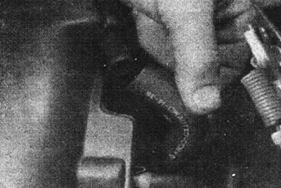
14.1. Disconnect the breather hose from the air intake housing.
2. Disconnect the vacuum hoses from the air temperature control flap. Mark the location of the hoses (see illustration).
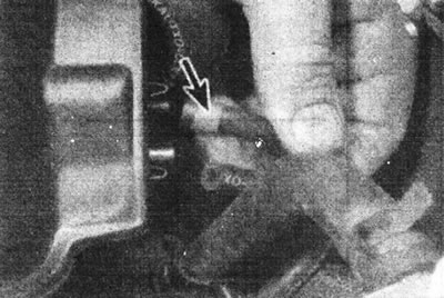
14.2. Disconnect the vacuum hoses from the air temperature control flap. Notice the bushing on the hose on the breather side.
3. Remove the three screws securing the air intake shroud to the throttle body (see illustration).
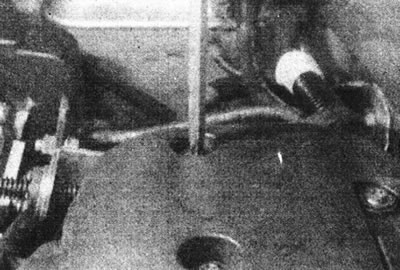
14.3. Remove the three screws securing the air intake casing.
4. Loosen the clamp and disconnect the air intake duct from the casing (see illustration).
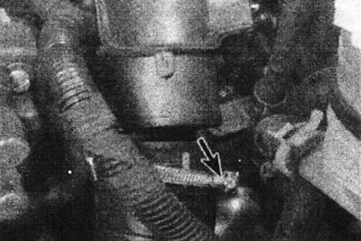
14.4. The air intake duct is secured to the casing with a clamp (marked with an arrow).
5. Remove the air intake casing and remove the gasket.
Installation
6. Install in reverse order, making sure the vacuum hoses are connected correctly. If necessary, use a new gasket on the top of the throttle body.
Throttle body
Note: A new throttle body gasket will be required during installation.
Removal
7. Disconnect the negative cable from the battery. Depressurize the fuel lines, see Chapter 7.
8. Depending on the model, remove the air cleaner housing or air intake housing from the top of the throttle body.
9. Disconnect the three multi-pin connectors from the throttle body (see illustrations).
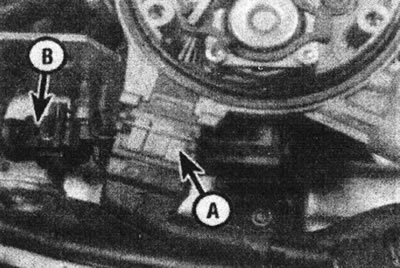
14.9a. Disconnect the injector/air temperature sensor wiring (A), and the idle speed motor/idle speed sensor wiring (B)...
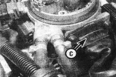
14.9b.... and the throttle potentiometer wiring (C).
10. Disconnect the fuel supply and return lines, remembering their location.
11. Disconnect the gas pedal cable.
12. Unscrew the four screws and remove the throttle body. Remove the gasket.
13. The two halves of the casing can be separated if necessary (see illustrations).
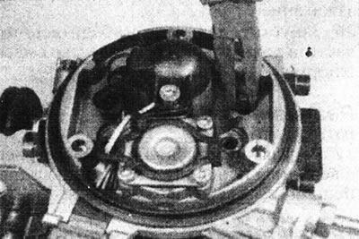
14.13a. Release the struts by squeezing them with pliers...
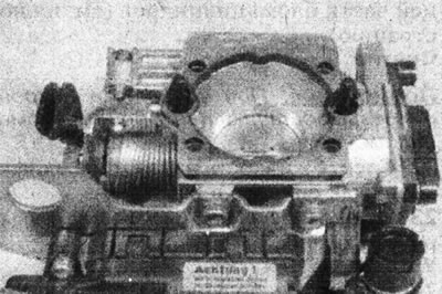
14.13b....and separate the two halves of the throttle body.
When assembling, replace the seals between them.
Installation
14. Install in reverse order, using a new gasket (see illustration).
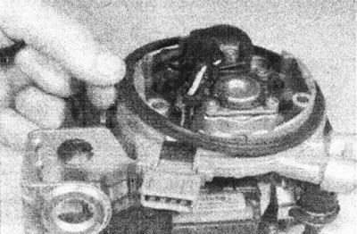
14.14. Install a new gasket on the top of the throttle body.
15. If the lower half of the throttle body has been replaced, the initial setting of the throttle potentiometer must be checked using the Renault XR25 tester.
Inlet air temperature sensor
Removal
16. Remove the air cleaner housing or air intake housing.
17. Disconnect the sensor wiring.
18. Loosen the fastening screw and release the sensor cover (see illustration).
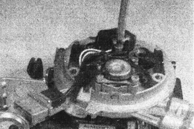
14.18. Unscrew the screw (size TX25) fastening the air temperature sensor cover.
19. Release the clips and remove the sensor together with the cover, wiring and connector (see illustration).
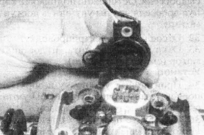
14.19. Remove the air temperature sensor assembly. The cap also serves as a connector for the fuel injector.
Installation
20. Install in reverse order.
Coolant temperature sensor
21. The location of the coolant temperature sensor may vary depending on the model. On E-series engines it is located on the left end of the cylinder head. On the F3P engine - on the rear of the cylinder block (see illustration).
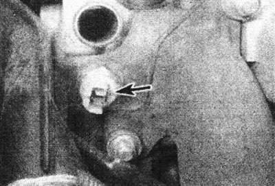
14.21. Coolant temperature sensor (marked with an arrow) at the rear of the cylinder block is the F3P engine.
Removal
Note: When installing, coat the sensor threads with a suitable sealant.
22. Drain the cooling system as described in Section 1.
23. Disconnect the electrical wiring and unscrew the sensor.
Installation
24. Apply a small amount of sealant to the sensor threads and screw it into position. Connect the wiring.
25. Fill the cooling system.
Fuel injector
Note: A new injector O-ring will be required during installation.
Removal
26. Remove the air cleaner housing or air intake housing.
27. Remove the intake air temperature sensor as described earlier in this Chapter.
28. Note the location of the injector, then remove it (see illustration).
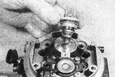
14.28. Remove the fuel injector.
Installation
29. Install in reverse order. Use new O-rings and coat them with silicone grease.
Idle speed drive motor
Removal
30. Remove the air cleaner housing or air intake housing.
31. Loosen the throttle body mounting screws. Carefully lift the throttle body to improve access to the motor.
32. Disconnect the electrical wiring.
33. Unscrew the three screws and remove the motor (see illustration).
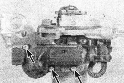
14.33. Idle speed drive motor mounting screws (marked with arrows).
Installation
34. Perform the installation in reverse order, then perform the initial installation as follows.
35. Place a spacer or feeler gauge approximately 5mm thick between the throttle lever and the motor rod. Turn on the ignition for a few seconds, then turn it off. Remove the gasket or dipstick, then cycle the ignition on and off again.
36. Start the engine and make sure that the idle speed and mixture quality are normal.
Fuel pressure regulator
37. The fuel pressure regulator is built into the upper half of the throttle body. If it is defective, replace it.
Throttle potentiometer
38. The throttle potentiometer is built into the lower half of the throttle body. If it is defective, replace it. The idle drive motor can be moved from the old half to the new one.
39. After replacement, it is necessary to check the initial setting of the potentiometer using the Renault XR25 tester.
Intake manifold pressure sensor
Removal
40. Unfasten the pressure sensor from the bracket on the bulkhead. Disconnect the wiring and vacuum hose (see illustration).
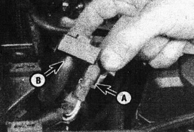
14.40. Removing the intake manifold pressure sensor - disconnect the connector (A) and the vacuum hose (B).
Installation
41. Install in reverse order.
Motion speed sensor
42. The speed sensor is mounted in the speedometer drive cable (see illustration).
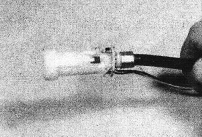
14.42. Speed sensor - at the end of the speedometer drive cable.
Intake manifold heater
Note: A new seal will be required during installation.
Removal
43. Some engines are equipped with an electric intake manifold heater.
44. Disconnect the electrical wiring from the heater, then remove the retaining ring and remove the heater from the manifold. Remove the seal.
Installation
45. Install in reverse order, use a new seal and ensure that the retaining ring is correctly seated in the groove.
Engine speed sensor (flywheel)
Removal
46. The sensor is located on the top of the clutch housing.
47. Disconnect the negative battery cable, then remove the air filter or intake duct to improve access.
48. Trace the wiring from the sensor and disconnect it.
49. Unscrew the two mounting bolts and remove the sensor from the top of the clutch housing (see illustration).
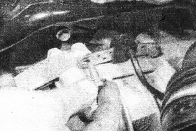
14.49. Loosen the engine speed sensor (flywheel) mounting bolt.
Installation
50. Install in reverse order. It is important to use only the special bolts that secure the sensor to the clutch housing, as they determine the correct distance from the flywheel.
Processor unit
Note: The following steps describe the procedure for models without air conditioning. On models with air conditioning, the processor unit is located in the passenger compartment under the glove compartment.
Removal
51. Disconnect the negative cable from the battery.
52. Remove the bracket, which is secured with two nuts and a bolt (see illustrations).
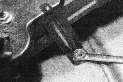
14.52a. To remove the CPU bracket, unscrew the nut here...
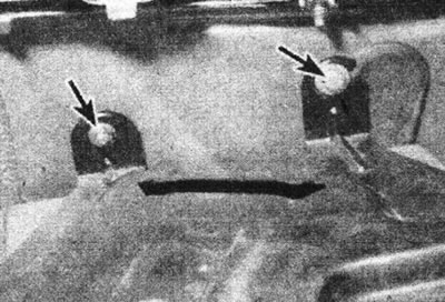
14.52b....and a nut and a bolt here (marked with arrows).
53. Unhook the fastening strap. Lift the bracket and processor unit together with the protective case (see illustration).
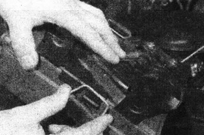
14.53. Unhook the fastening belt and release the processor unit housing.
54. Open the protective casing. Disconnect the connector and remove the unit (see illustration).
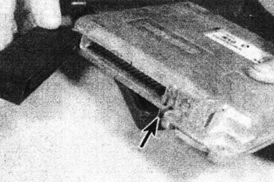
14.54. Press the latches (marked with an arrow), and disconnect the multi-pin connector from the processor unit.
Installation