



Contents: Inlet air temperature sensor 🠛 Coolant temperature sensor 🠛 Engine speed sensor 🠛 Fuel injector 🠛 Fuel pressure regulator 🠛
1. Renault dealers use special diagnostic equipment (XR25 unit), which is connected to the diagnostic coupling on the main casing in the car's interior. This device allows you to quickly and comprehensively diagnose the system. It is also the only means of checking the functioning of the processor unit.
2. The following points provide information on some checks to be carried out in the event of a malfunction.
3. The digital multimeter must be a modern type with an internal resistance of at least 10 megohms. Do not use analog devices (switch), which may have unacceptably low internal resistance.
4. Idle speed control motor, throttle potentiometer, manifold pressure sensor, vehicle speed sensor (where is it installed), or the processor unit cannot be checked in any way.
5. Before checking the serviceability of individual components, make sure that all system connectors are not corroded and are securely connected, and that all fuel, air and vacuum hoses are in good condition. Also remember that idle problems can simply be due to improper throttle cable adjustment.
6. If a defective component is found, replace it as described in next Chapter.
Inlet air temperature sensor
7. Remove the air filter or air intake cover.
8. Disconnect the intake air temperature sensor wiring.
9. Connect an ohmmeter to terminals A1 and A4 and measure the resistance of the temperature sensor (see illustration).
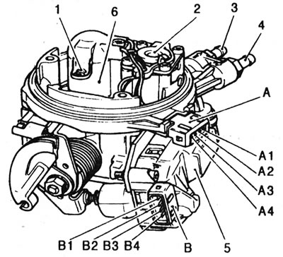
13.9. Terminal and component identification - central fuel injection system: 1 - Air temperature sensor; 2 - Fuel pressure regulator; 3 - Fuel return pipe; 4 - Fuel supply pipe; 5 - Idle speed drive motor; 6 - Nozzle; A - Air temperature sensor/injector connector; A1 - Air temperature sensor; A2 - Nozzle (+); AZ - Injector (-); A4 - Air temperature sensor; B - Idle speed motor/idle speed sensor connector; B1 - Motor power supply; B2 - Motor power supply; B3 - Idle speed sensor; B4 - Idle speed sensor.
The permissible values are given in Specifications. Using a hair dryer, heat the sensor and make sure that its resistance decreases with increasing temperature.
Coolant temperature sensor
10. To check the serviceability, see Chapter 8 of Section 3, and for resistance values see. v Specifications at the beginning of this Section.
Engine speed sensor
11. With the ignition off, disconnect the speed sensor signal wire (B) (see illustration 13.9). Check the sensor resistance by connecting an ohmmeter to terminals 4 and 5. The result should be within 200±50 ohms. Otherwise, replace the sensor.
12. Using a feeler gauge, check that there is a gap of 1.0±0.5 mm between the end of the sensor (P) and the flywheel (V). If the gap is incorrect, replace the sensor.
Fuel injector
13. Check the resistance of the injector winding (terminals A2 and A3) (see illustration 13.9).
14. If the resistance does not correspond to the given data, remove the intake air temperature sensor (Chapter 14) and repeat the measurement directly at the injector terminals.
15. If the resistance is normal, then the wiring between the connector and the injector is faulty. If the resistance is incorrect, then the injector is defective.
16. If necessary, try cleaning the injector with a special product by adding it to the fuel tank.
Fuel pressure regulator
17. Checking the serviceability of the fuel pressure regulator is part of the fuel pressure check procedure (Chapter 8).