



Note: A new sensor seal will be required during installation.
Removal
1. Disconnect the negative cable from the battery. Recline the rear seat and remove the fuel gauge access cover.
2. Disconnect the hose and multi-pin connectors from the top of the sensor, marking their location to avoid confusion during installation (see illustration).
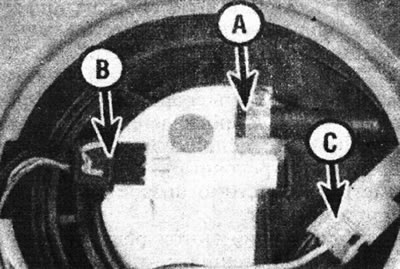
10.2 Fuel level sensor connections - breather hose (A), sensor wiring (B) and pump wiring (C).
3. Unscrew the ring nut using the tool shown (see illustration 9.11a).
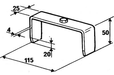
9.11a. Dimensions of the tool for unscrewing the ring nut (in mm).
Remove the nut and take out the sensor (see illustration).
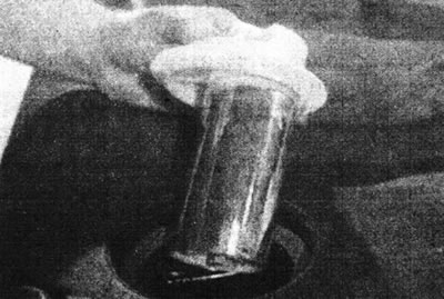
10.3. Remove the fuel level sensor.
Checking the serviceability
4. Turn the sensor over: you should be able to hear the float moving.
5. Connect an ohmmeter to the terminals and observe the resistance change from empty to full. Refer to the accompanying illustration.
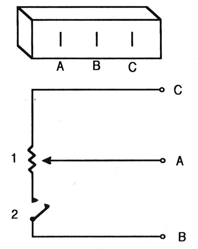
10.5. Fuel level sensor terminal designations (sensor in vertical position) and a diagram of internal connections.
The results should be approximately as follows:
| Terminals | "Empty" | "Enough" |
| A - B | 10 Ohm | Infinity |
| A - C | 290 Ohm | 0.7 Ohm |
| B - C | 300 Ohm | Infinity |
6. If the instrument readings do not change as described, and if they change abruptly, the sensor should be replaced.
Installation
7. Install in reverse order. Use a new O-ring.