



Note: See warning at end Chapters 1. To perform the test, you will need a suitable pressure gauge and a T-connector.
1. Depressurize the fuel system as described in Chapter 7.
2. Remove the air cleaner housing or air intake housing to improve access to the throttle body.
3. Using a T-connector, connect the pressure gauge (measurement range 0-3 bar) to the fuel supply line where it connects to the throttle body (see illustration).

8.3. Checking the fuel system pressure - central fuel injection: A - Fuel supply pipe; B - Fuel return pipe.
4. Turn on the fuel pump by short-circuiting terminals 3 and 5 on the fuel pump relay (installed in the processor unit housing or in the relay unit in front of the upper support of the left suspension strut) (see illustration).
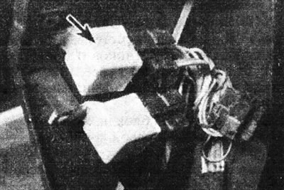
8.4. On this model, the fuel pump relay (marked with an arrow) is located in the relay block. On other models it may be located in the processor unit housing.
The fuel pump relay can be identified by the thick wires connected to terminals 3 (red or red and white wire) and 5 (brown or white wire).
5. Note the pressure on the pressure gauge. It must correspond to the given in Specifications the value of the regulated pressure.
6. Momentarily pinch the fuel return line. Notice the pressure. It must correspond to the value of unregulated pressure given in the Specifications.
7. If the pressure is below normal, check the pump performance as described in Chapter 9, to determine where the fault is - in the pump or in the pressure regulator. If the pressure is higher than normal, the fault may only be in the pressure regulator.
8. Remove the jumper from the fuel pump relay. Depressurize the fuel system and disconnect the pressure gauge, then restore the connections.