



Note: When installing, use a new head gasket and new cylinder head bolts, and a new valve cover gasket may also be required - see text.
Removal
1. The following procedure describes the removal and installation of the cylinder head together with the manifolds and high pressure fuel pump.
2. Disconnect the negative cable from the battery (see Section 5A). On models with the F9Q engine, unscrew the mounting nuts and remove the engine soundproof cover.
Warning: If your car's radio is coded, make sure you have the key code before disconnecting the battery.
3. Drain the cooling system, including the cylinder block, as described in Section 1.
4. To improve access, unscrew the reinforcement rod (where available) between the front suspension towers.
5. Remove the auxiliary drive belt (Section 1). On models with F9Q engines and air conditioning, remove the auxiliary drive belt tensioner mounting plate, then remove the fuel pump/generator mounting bolt.
6. Unscrew the ground strap from the rear of the engine.
7. On models with the F8Q engine, disconnect the accelerator pedal cable from the high-pressure fuel pump and move the cable away from the engine, making a note of its route (see Section 4D if necessary).
8. Loosen the banjo connection and disconnect the fuel supply line from the fuel pump (see illustration).
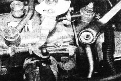
9.8. Unscrewing the fuel supply line banjo connection.
Remove the sealing washers. Plug the open end of the tube and the hole in the pump to prevent dirt from entering.
9. Remove the retaining clip and disconnect the main fuel return hose from the pipe on the high pressure fuel pump. Thread the hose through the rear mounting eye on the cylinder head and move the hose away from the engine. Cap the open ends of the tube and hose to prevent dirt from entering.
10. Disconnect and remove the air duct connecting the air filter to the intake manifold or turbo generator (please note that you will also need to disconnect the breather hoses that are connected to the air duct).
11. On turbocharged engines, disconnect and remove the air duct connecting the air cooler to the turbo generator.
12. Remove the toothed drive belt as described in Chapter 5, and the tensioning mechanism as described in Chapter 6. To support the engine/transmission, Renault vehicles use a special holder installed under the right front side of the cylinder block and engine subframe, and an additional bracket secured below the water pump.
13. Unscrew the hose retainer from the front of the fuel pump bracket and move the hoses and retainer away from the pump.
14. Disconnect the breather hoses from the oil separator, and on turbocharged engines, also disconnect the hose from the boost pressure corrector on the fuel pump. Also disconnect the ends of these hoses from the manifold.
15. Unscrew one hose retainer from the front mounting eye and one from the vacuum pump and remove the hose assembly from the engine.
16. On non-turbocharged engines, disconnect the coolant hose from the thermostat housing.
17. On turbocharged engines, unscrew the thermostat housing from the cylinder head and move it to the side without disconnecting the hoses and wiring to the sensor (see illustration).
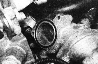
9.17. Unscrew the thermostat housing and move it to the side - turbocharged engines.
18. Disconnect the coolant hose from the left rear corner of the cylinder head and move it away from the head.
19. Disconnect the hose from the vacuum pump (see illustration).
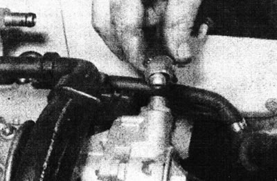
9.19. Disconnecting the vacuum pump hose.
20. Disconnect all electrical wiring from the fuel pump. Mark all connections to avoid confusion during installation.
21. Disconnect the electrical supply wires from the glow plugs.
22. On non-turbocharged engines, disconnect the wiring connector from the coolant temperature gauge/warning lamp sensor assembly located in the thermostat housing below the vacuum pump.
23. Disconnect all pipes and hoses from the manifolds and turbogenerator, following the relevant Chapters Section 4D. Mark all pipes and hoses to avoid confusion during installation.
24. Where applicable, unscrew the hose retainers from the manifolds and around the head and move the hoses to the side.
25. On turbocharged engines, remove the two bolts securing the turbocharger inlet elbow to the bracket on the transmission. Remove the nut and bolt securing the mounting bracket to the turbo generator and inlet elbow and remove the elbow.
26. Remove the bolts securing the inner upper timing belt cover to the cylinder block.
27. Remove the bolt securing the intermediate pulley of the toothed drive belt, which passes through the inner cover.
28. Remove the front part of the exhaust system as described in Section 4D.
29. On turbocharged engines, loosen the union nut securing the turbo generator oil feed pipe to the cylinder block and remove the pipe.
30. On turbocharged engines, remove the bolts securing the turbo generator bracket to the turbo generator and engine and remove the bracket.
31. If not already done, remove the dowel pin from the cylinder block and rotate the crankshaft counterclockwise a quarter turn to position all four pistons in the middle of the cylinders.
32. Working in the reverse order to that shown in Illustration 9.51, gradually loosen the cylinder head mounting bolts one half turn at a time until they can be removed by hand (see illustration).
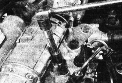
9.32. Loosening of the cylinder head mounting bolt.
Throw away the bolts.
33. The cylinder head together with the parts attached to it is very heavy, so it is recommended to use a winch when removing it from the cylinder block.
34. Raise your head (together with manifolds, fuel pump and inner upper timing belt cover) up from the cylinder block (see illustration).
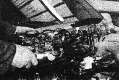
9.34. Lifting the cylinder head from the engine - turbocharged engine.
If the mounting pins are loose, remove them and fold them together with the head.
35. If required, collectors, turbo generator (where it is applied) and the fuel pump can be removed from the head, following the relevant Chapters Section 4D.
Inspection
36. The mating surfaces of the cylinder head and block must be completely clean. Using a scraper, remove all traces of gasket and carbon deposits and clean the tops of the pistons. Work especially carefully with the aluminum cylinder head, as the soft metal can be easily damaged. Also, be careful not to let dirt get into the oil and water passages - this is especially important for the lubrication chain, as carbon deposits can block the oil supply to the camshaft and crankshaft bearings or rocker arms. Use masking tape and paper to seal the water and oil passages and bolt holes in the cylinder block. Clean the piston heads in a similar manner.
37. Check the block and head for nicks, deep scratches and other damage. If there are small scratches, they can be carefully removed with a file. More serious damage can be repaired by resharpening, but this work should be entrusted to a specialist.
38. Using a ruler placed on its edge, check the warpage of the cylinder head. See Section 2F if necessary.
39. Clean all bolt holes in the block. Make sure there is no oil left in them, otherwise there is a risk that the block may crack under hydraulic pressure when tightening the bolts.
40. Inspect the bolt threads and the threads in the cylinder block for damage. If necessary, use a tap of the appropriate size to renew the threads in the block and use a thread-cutting die to clean the threads on the bolts. It is recommended to replace the bolts after each removal.
Selecting a gasket
41. Turn the crankshaft so that pistons No. 1 and No. 4 are in a position just below TDC (below the surface of the cylinder block). Place the dial micrometer on the cylinder block and set it to zero on the block surface. Position the micrometer probe at the center of piston No. 1, then slowly rotate the crankshaft back and forth until the piston passes TDC, noting the highest reading on the micrometer. Write down the result obtained.
42. Repeat this procedure on piston #4, then turn the crankshaft half a turn (180°) and repeat the procedure on pistons #2 and #3 (see illustration).
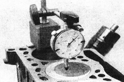
9.42. Measuring the piston protrusion height.
All measurements must be taken on the longitudinal axis of the crankshaft (to eliminate errors due to piston tilt).
Note: The holes indicating the thickness of the gasket are located 25 mm from its edge. Ignore other openings outside this area.
43 If a micrometer is not available, piston protrusion can be measured using a ruler and feeler gauge or a caliper. However, these methods are less accurate and therefore cannot be recommended.
44 Use the largest measured piston protrusion value to determine the appropriate shim. Thickness marking holes are located in the front corner of the gasket, on the flywheel side (see illustrations).
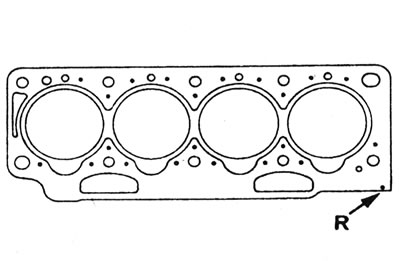
9.44a. Location of cylinder head gasket thickness mark (R).
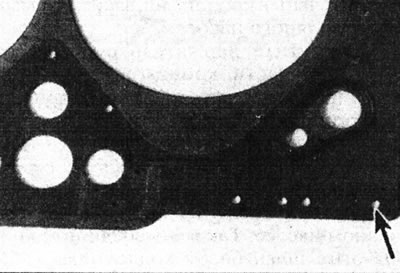
9.44b. Gasket thickness mark - "1 hole".
| Piston protrusion | Gasket designation |
| F8Q Non-Turbocharged Engines: Up to 0.868 mm | 2 holes |
| 0.868 - 1.000 mm | 1 hole |
| More than 1,000 mm | 3 holes |
| F8Q Turbocharged Engines: Up to 0.073 mm | 2 holes |
| 0.073 - 0.206 mm | 1 hole |
| More than 0.206 mm | 3 holes |
| F9Q engines: Up to 0.653 mm | 2 holes |
| 0.653 - 0.786 mm | 1 hole |
| More than 0.786 mm | 3 holes |
Note: The holes indicating the thickness of the gasket are located 25 mm from its edge. Ignore other openings outside this area.
Cylinder head mounting bolts
45. The manufacturer recommends replacing the cylinder head bolts after each removal.
Installation
46. Install the collectors and turbo generator (where it is applied) and the high-pressure fuel pump to the cylinder head, in accordance with the relevant Chapters Section 4D.
47. Remove the dowel pin from the cylinder block and turn the crankshaft clockwise until pistons No. 1 and No. 4 pass the bottom dead center position and begin to rise, then place them in the middle of the cylinders (this is necessary to prevent the possibility of the piston hitting the valves. Do not turn the crankshaft any further until the timing belt has been installed.
48. Make sure the dowel pins are in place in the cylinder block, then position the gasket with the correct orientation (see illustration).
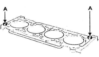
9.48. Position of the cylinder head mounting pins (A).
49. Lower the head onto the cylinder block. The inner upper timing belt cover must be properly connected to the lower inner cover on the cylinder block. Disconnect the lifting device and winch. On F8Q engines, ensure that the swirl chambers do not fall out of their sockets in the cylinder head.
50. Lightly lubricate the new cylinder head bolts. Wait for the excess oil to drain, then insert the bolts with washers and tighten them by hand.
51. In the sequence shown, tighten the cylinder head mounting bolts to the specified tightening torque Specifications (see illustration).
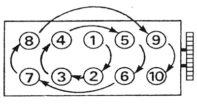
9.51. Sequence of tightening the cylinder head bolts.
Please note, on non-turbocharged F8Q engines or F9Q engines, there is no need to re-tighten the bolts. On turbocharged F8Q engines, at the end of assembly, after the first engine start, it is necessary to additionally tighten the bolts, having first warmed up the engine to normal operating temperature and waited until it has cooled down completely.
52. On turbocharged engines, install the turbo generator bracket and tighten the mounting bolts.
53. On turbocharged engines, install the turbocharger oil feed pipe/hose and tighten the coupling onto the cylinder block.
54. Install the front part of the exhaust system as described in Section 4D.
55. Install the timing belt idler pulley mounting bolt.
56. Install the bolts securing the inner upper timing belt cover to the cylinder block, then install the timing belt tensioner as described in Chapter 6.
57. Install the new timing belt as described in Chapter 5.
58. On turbocharged engines, inspect the O-ring in the turbocharger inlet elbow and replace it if necessary. Install the elbow and bracket.
59. Install the hose clamps to the manifolds as noted before removal.
60. Connect all pipes and hoses to the manifolds and turbo generator as noted before removal.
61. On non-turbocharged engines, connect the wiring harness to the coolant temperature gauge/warning lamp sensor assembly.
62. Connect the power wires to the glow plugs.
63. Connect all electrical wiring to the high pressure fuel pump.
64. Connect the engine ground strap to the rear mounting eye.
65. Connect the coolant hose to the cylinder head and the hose to the brake system vacuum pump.
66. Connect the air ducts to the air cleaner, intake manifold, turbo generator and air cooler, where available. Make sure all hoses are connected properly.
67. On turbocharged engines, inspect the O-ring between the thermostat housing and the cylinder head and replace it if necessary. Install the thermostat housing to the cylinder head.
68. On non-turbocharged engines, connect the coolant hose to the thermostat housing.
69. Connect the crankcase breather hoses and, on turbocharged engines, also connect the boost pressure correction hose. Install the brackets onto the engine mounting eye and vacuum pump.
70. Install the hose bracket to the high pressure fuel pump bracket.
71. Route the main fuel return hose through the engine mounting eye and connect it to the pipe on the high pressure fuel pump.
72. Connect the fuel supply hose to the fuel pump.
73. Connect the gas pedal cable as described in Section 4D.
74. Where applicable, install the reinforcement rod to the front suspension strut towers.
75. Make sure that the drain plug in the cylinder block (where available) securely fastened, then fill and bleed the cooling system as described in Section 1.
76. Install the auxiliary drive belt tensioner and bracket, then the drive belt (see Section 1 if necessary).
77. Connect the negative cable to the battery.
78. Bleed the fuel system as described in Section 4D.
79. On turbocharged engines, before starting the engine, perform the procedure described in Section 4D (filling the turbogenerator lubrication circuit). On models with the F9Q engine, install the engine sound cover.
80. On turbocharged F8Q engines, tighten the cylinder head bolts to final torque (see Specifications), pre-warming the engine to normal operating temperature and waiting until it has cooled down completely. It may be necessary to remove the upper bracket of the right engine mount (see Chapter 13) to gain access to one of the bolts.