



Warning: If the timing belt breaks during operation, it can cause extensive engine damage. Replace the belt at the intervals specified in Specifications in Section 1, or earlier if you have any doubts about its condition.
Note: F8Q 620 and early F8Q 784 engines are equipped with a toothed drive belt "HTD", while late F8Q and all F9Q engines are equipped with a belt with a different tooth profile "HTD2". Whenever the toothed drive belt is replaced always make sure you purchase the correct type of belt to match the sprockets - the same applies to any sprocket that will be replaced.
Note: To check the timing belt tension, you'll need a special tool—see text. To remove the crankshaft pulley, you may need a suitable puller.
Removal
1. Disconnect the negative cable from the battery.
Warning: If your car's radio is coded, make sure you have the key code before disconnecting the battery.
2. Jack up the front right corner of the car and remove the wheel and wheel arch liner (secured with plastic staples). Where present, remove the lower engine shield.
3. On models with F8Q engines, remove the mounting bolts and remove the upper plastic drive belt/right engine mount cover, noting the location of the bolted-on retainers. On models with F9Q engines, loosen the mounting nuts and remove the engine sound cover, then disconnect the wiring connector from the injection system control unit, loosen the two mounting bolts and move the control unit to the side.
4. Remove the accessory drive belt as described in Section 1. To improve access, unscrew the reinforcement rod (where available) between the front suspension towers.
5. Unscrew the crankshaft pulley bolt.
6. Remove the bolt and pulley from the end of the crankshaft (see illustrations).
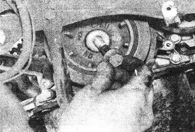
5.6a. Remove the crankshaft pulley bolt...
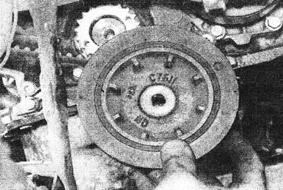
5.6b....and pulley.
7. To improve access, remove the two bolts securing the fuel filter assembly to the body panel, then release the filter hoses from their mounts on the engine. The assembly can be moved to the side (on the top of the engine).
8. Temporarily install the crankshaft pulley bolt. Set piston No. 1 to TDC on the compression stroke and insert the dowel pin to check the crankshaft position as described in Chapter 3.
9. Now you need to remove the right front engine mount so that you can remove the toothed drive belt; therefore, the engine under the sump must be supported by a jack with a wooden block placed between them to increase the support area.
10. Loosen the nut securing the upper suspension bracket to the travel limiter/rubber pad assembly - refer to the Chapter 13.
11. Remove the three bolts securing the upper mount bracket to the main mount on the engine, then remove the bracket.
12. Unscrew the travel limiter/rubber cushion assembly from the body. On turbocharged F8Q engines, also remove the rear suspension tie rod (Chapter 13) and unscrew the bolts securing the exhaust outlet pipe to the exhaust manifold (see section 4D). Release the drain pipe and support it.
13. Loosen the mounting bolts and remove the outer drive belt cover that covers the high pressure fuel pump sprocket (see illustration).
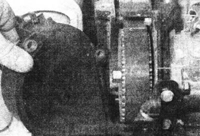
5.13. Removing the drive belt cover from the fuel pump sprocket.
14. Unscrew the mounting bolts, marking the location of the holders attached with bolts, and remove the cover that covers the camshaft sprocket (see illustrations).
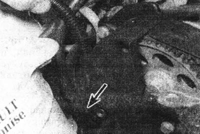
5.14a. Note the location of the bolted holders...
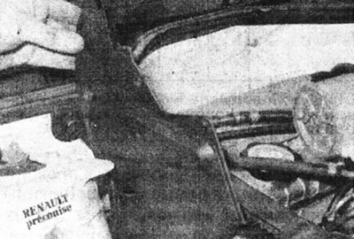
5.14b....and remove the drive belt cover from the camshaft sprocket.
Note: On engines with a MAA fuel pump sprocket, the actual timing mark on the pulley may differ from that shown - see text
15. Set piston No. 1 to TDC on the compression stroke (see point 8), and note the position of the timing mark on the high pressure fuel pump sprocket. On engines with a MAA fuel pump sprocket, the timing mark on the pulley may differ from that shown for a solid pulley. In this case, take into account the type of label and its location to facilitate subsequent installation. Please note that on solid sprocket models there are two alignment marks on the pulley. The mark used depends on which fuel pump is installed (Bosch or Lucas) (see illustrations).
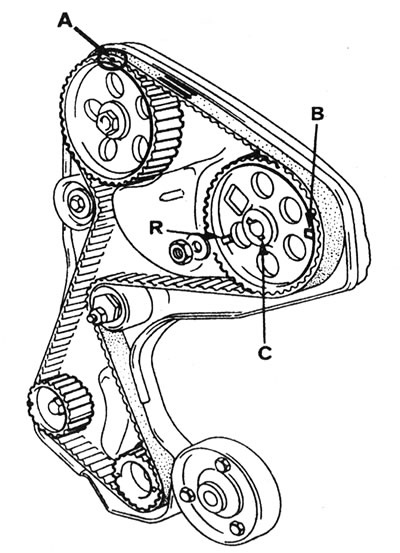
5.15a. When piston #1 is at TDC, the timing marks on the camshaft and fuel pump sprockets should be positioned as shown - F8Q 620 engine: A - Mark on the camshaft sprocket (aligned with the indicator on the outer drive belt cover - removed here); B - Mark on the fuel pump sprocket - used with the Bosch pump; C - Slot for a woodruff key; R - Mark on fuel pump sprocket - used with Lucas pump.
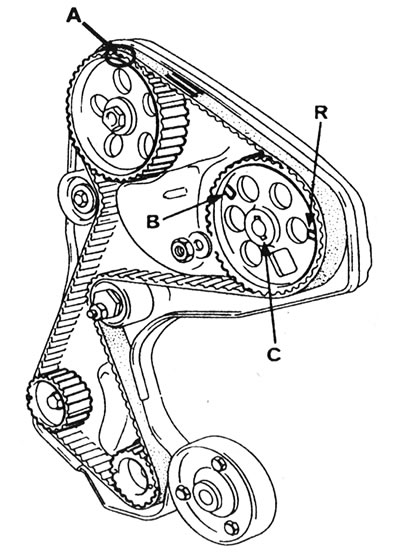
5.15b. When piston #1 is at TDC, the timing marks on the camshaft and fuel pump sprockets should be positioned as shown - F8Q 784, F8Q 786 and F8Q 788 engines: A - Mark on the camshaft sprocket (aligned with the indicator on the outer drive belt cover - removed here); B - Mark on fuel pump sprocket - used with Bosch pump; C - Slot for a woodruff key; R - Mark on fuel pump sprocket - used with Lucas pump.
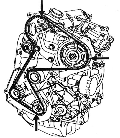
5.15s. When piston #1 is at TDC, the timing marks should be positioned as shown - F9Q engines.
16. If the old belt will be used (contrary to Renault's recommendation), install it so that the arrows match the direction of rotation. Also note that the belt should have transverse stripes that correspond to the timing marks on the camshaft sprockets, high-pressure fuel pump and crankshaft.
17. Loosen the mounting nut and bolt, then move the tensioner back to reduce the belt tension (see illustration).
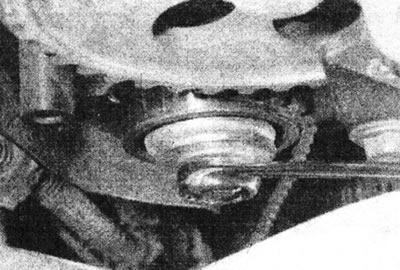
5.17. Loosen the toothed belt tensioner mechanism nut.
Tighten the nut again.
18. Remove the belt first from the camshaft sprocket, then from the fuel pump sprocket, roller, crankshaft pulleys and intermediate shaft.
19. Do not turn the camshaft or crankshaft until the timing belt is in place.
Inspection
Note: Renault recommends replacing the timing belt each time it is removed. If the belt tension is checked with a special tool, it will be suitable for further use only if the tension is within the limits specified in Specifications permissible deviations. If the tension is in the lower range of acceptable values, the belt cannot be tensioned further and must be replaced.
20. Clean the sprockets, idler pulley and tensioner mechanism and wipe them dry - do not use excessive amounts of solvent when cleaning the idler pulley and tensioner mechanism, otherwise the bearing grease may be removed. Also clean the inner timing belt cover and the mating surface of the cylinder head and block.
21. Carefully inspect the toothed drive belt along its entire length, especially at the base of the teeth. Replace the belt if it is contaminated with oil or grease. Replace all leaking seals. The belt must be replaced when the maximum mileage given in Section 1.
Installation
22. Make sure that the piston of cylinder No. 1 is in the TDC position and the dowel pin is inserted into the crankshaft. To be able to adjust the tensioner, screw a 6mm bolt into the threaded hole in the inner timing belt cover (see illustration 5.26).
23. Align the stripes on the belt with the marks on the crankshaft, camshaft and high-pressure fuel pump sprockets; the direction of the arrows on the belt must match the direction of engine rotation. Install the timing belt on the crankshaft sprocket, then on the idler pulley, high pressure fuel pump sprocket, camshaft sprocket, tensioner and idler shaft sprocket (see illustrations).
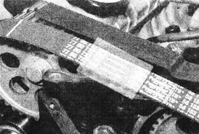
5.23a. The arrows on the belt must point clockwise.
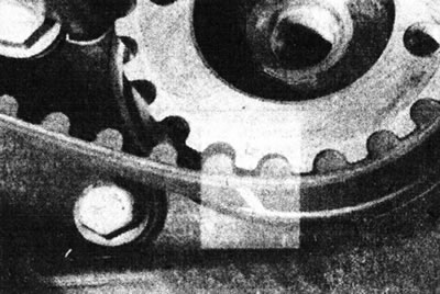
5.23b. Align the stripes on the belt with the marks on the crankshaft sprocket...
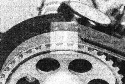
5.23 sec....camshaft sprocket...
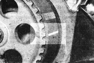
5.23d....and the fuel pump sprocket - engine with Lucas pump.
24. Make sure all timing marks are aligned and remove any slack from the timing belt by tightening the bolt on the inner cover.
Note: To check, count the number of teeth on the timing belt between the timing mark on the camshaft pulley and the timing mark on the fuel pump pulley - if the valve timing is correct, there should be 29 teeth for F8Q engines and 30 teeth for F9Q engines.
25. Now it is necessary to adjust the belt tension, this can only be done accurately using the Renault Mot.1273 tool (SEEM C. Tronic 105.6) (see illustration).
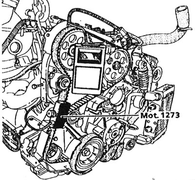
5.25. Using the Renault Mot. 1273 tool to check the timing belt tension.
If this equipment is not available, adjust the belt tension as far as possible using the method described below and then contact a Renault dealer as soon as possible to have the tension checked. Do not drive on a long trip or at high speed until the timing belt tension has been checked.
26. If the adjustment is incorrect, the tensioner mechanism must be moved by loosening the nut and turning the bolt on the inner timing belt cover (see illustration).
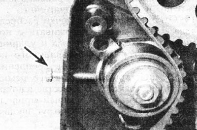
5.26. Bolt M6 on the inner cover of the timing belt.
27. Once the belt is tensioned correctly, tighten the tensioner nut to the specified tightening torque Specifications. Loosen the bolt on the inner timing belt cover so that it no longer contacts the tensioner pulley bracket.
28. Remove the crankshaft dowel pin, then install the crankshaft pulley and mounting bolt.
29. Make sure the crankshaft is set to TDC (to do this, insert the dowel pin), then remove the dowel pin and rotate the crankshaft two full revolutions in the normal direction of rotation, returning it to the TDC position. Reinsert the dowel pin into the cylinder block.
30. Temporarily install the outer drive belt cover that covers the camshaft sprocket and ensure that the timing mark on the pulley is aligned with the pointer on the cover (see Chapter 3).
31. Recheck the belt tension as described above. If the tension is incorrect, the installation and checking procedure must be repeated.
32. After tensioning the belt, remove the M6 bolt from the inner cover and remove the dowel pin from the cylinder block. Install the plug into the cylinder block and tighten it and the tensioner mounting bolt securely.
33. Check the injection timing as described in Section 4D.
34. Install the upper outer drive belt covers.
35. Attach the travel limiter/rubber engine mount assembly to the body and to the upper engine bracket as described in Chapter 14. Remove the jack or other device that was used to support the engine.
36. Install the fuel filter assembly and secure the hoses. On turbocharged F8Q engines, install the rear tie rod (Chapter 13) and the exhaust outlet pipe (see Section 4D).
37. Install the auxiliary drive belt as described in Section 1.
38. Where applicable, install the reinforcement rod to the front suspension towers.
39. On models with F8Q engines, install the upper plastic drive belt/right hanger cover. On models with F9Q engines, install the injection control unit and wiring connector, then install the engine sound cover.
40. Where fitted, install the engine undershield, then the wheel arch liner and wheel, then lower the vehicle to the ground.
41. Connect the negative cable to the battery.