



Note: A new drive belt side oil seal and a new valve cover gasket may be required during installation. The camshaft bearing caps will require sealant, and the bearing cap mounting bolts will require locking compound.
Removal
1. Remove the camshaft sprocket as described in Chapter 6.
2. Remove the timing belt tensioner mechanism as described in Chapter 6 (see illustration).
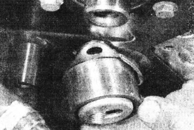
8.2. Remove the timing belt tensioner mechanism.
3. Remove the two bolts securing the inner upper timing belt cover to the cylinder head (see illustration).
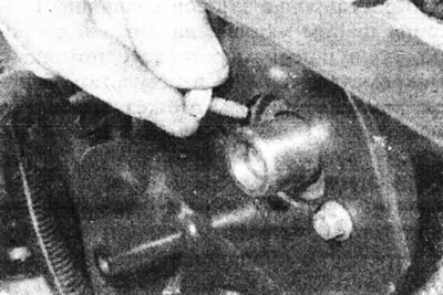
8.3. Remove the bolts securing the inner upper timing belt cover to the cylinder head.
4. Remove the lower bolts securing the inner upper timing belt cover to the cylinder block.
5. Unscrew the bolt securing the intermediate pulley of the toothed drive belt, which also passes through the inner cover.
6. Separate the inner cover and remove it if possible.
7. Remove the vacuum pump as described in Section 9.
8. To improve access, release the hoses that run along the top of the valve cover from their mountings and move them to the side. If fuel lines become disconnected, plug the open ends to prevent dirt from entering.
(This article is taken from the website: RENAULTBOOK.ru)
9. Loosen the nuts or bolts and remove the valve cover. Remove the gasket.
10. Using a micrometer, measure the axial clearance of the camshaft and compare it with the value given in Specifications (see illustration).
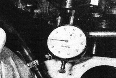
8.10. Measuring the axial clearance of the camshaft.
11. If you are installing an old camshaft, it is recommended that you measure the valve clearances at this stage as described in Chapter 4.
12. Check the camshaft bearing caps for marks to avoid confusion during installation; if necessary, mark them so that they can be installed in their original locations. Number the lids.
13. Gradually loosen the bearing cap mounting bolts and posts, evenly reducing the valve spring pressure. Remove the bolts and struts (remembering their location) and then the bearing caps. Please note that bearing cap #1 is secured with two posts and two additional bolts.
14. Lift the camshaft together with the oil seal (see illustration).
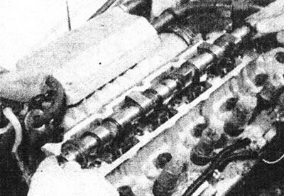
8.14. Raise the camshaft.
15. Remove the tappets with washers (see illustration).
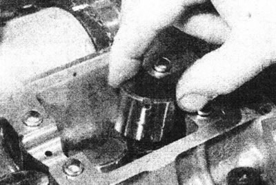
8.15. Remove the tappets.
Place them in a box with compartments, or on a clean piece of cardboard divided into eight sections. Record the thickness of the adjusting washers - this information will be needed later when adjusting the valve clearances. The thickness of the washer is indicated on the bottom side, but it is better to measure it with a micrometer, since due to wear the thickness of the washer may be less than indicated on it.
Inspection
16. Inspect the camshaft bearing running surfaces and cam lobe running surfaces for wear, corrosion or scratches. Replace the camshaft if such damage is detected.
17. After each removal, replace the camshaft oil seal on the drive belt side. Before installing a new oil seal, lubricate its sealing lips.
18. Inspect the working surfaces of the camshaft bearings in the cylinder head and bearing caps. If there are deep scratches or other damage, the cylinder head must be replaced.
19. Inspect the tappets and adjusting washers for scratches, corrosion and worn areas. Replace as necessary.
Installation
20. Install all pistons in the middle of the cylinders as described for removing the sprocket in Chapter 6.
21. Lubricate the tappets and install them in their places. Install the washers with the marked side down.
22. Lubricate the camshaft bearings. Place the camshaft together with the oil seal on the cylinder head. The oil seal must be positioned so that it is flush with the surface of the cylinder head.
23. Apply sealant (CAF 4/60 THIXO, Rhodorseal 5661 or other suitable) on the mating surfaces of the cylinder head at the installation locations of the right and left camshaft bearing caps (No. 1 and No. 5).
24. Install the covers in their places, ensuring that the right oil seal is correctly positioned in the bearing cover.
25. Apply a few drops of locking compound to the threads of the bearing cap bolts and posts. Install the bolts and struts and gradually tighten them to the torque specified in the Specifications.
26. If a new camshaft is installed, measure the end clearance and ensure that it complies with the data given in Specifications.
27. Install the vacuum pump as described in Section 9.
28. Install the inner upper timing belt cover, then install and tighten the bolts securing it to the cylinder block and head.
29. Install and tighten the timing belt idler pulley assembly bolt.
30. Install the timing belt tensioner mechanism, ensuring that the protrusion on the cylinder block fits into the hole in the tensioner bracket.
31. Install the camshaft sprocket as described in Chapter 6.
32. Check the valve clearances as described in Chapter 4, and, if necessary, adjust them by selecting washers of the required thickness.
33. Install the valve cover, using a new gasket if necessary, and tighten the mounting nuts or bolts to the torque specified in the Specifications.
34. Install/connect hoses that were moved to improve accessibility. If the fuel lines were disconnected, reconnect them and then bleed the fuel system as described in Section 4D.
35. Connect the negative cable to the battery.