
English Русский
Български
Беларускі
Український
Српски
Hrvatski
Română
Polski
Slovenský
Magyar
Bookmark Contacts Articles Sitemap
Company vehicles Peugeot Company vehicles Opel Company vehicles Skoda Company vehicles Land Rover Company vehicles Mitsubishi Company vehicles Volkswagen Company vehicles Honda
RenaultBook.ru


Duster   Fluence   Kangoo   Laguna   Logan   Megane   Sandero   Scenic   Symbol   Clio   Other
Clio 1 (1990-1998)

Vacuum booster unit — checking for proper operation, removal and installation (Renault Clio 1)

  • Main
  • Clio
  • Clio 1 (1990-1998)
  • Chassis, running gear
  • Brake system
  • Vacuum booster unit — checking for proper operation, removal and installation
0
Contents: Checking the serviceability 🠛 Removal 🠛 Installation 🠛

Checking the serviceability


1. To check the function of the booster, press the brake pedal several times to relieve the vacuum, then start the engine while keeping the pedal depressed. When the engine starts, the pedal should move down noticeably as the vacuum builds up. Let the engine run for at least two minutes, then turn it off. Press the brake pedal again several times - the first time you press it, the pedal should move easily, but with each subsequent press, its elasticity should increase and the pedal travel should decrease.

2. If the amplifier does not operate as described, inspect its check valve (see Chapter 4). If the check valve is OK, try replacing the booster air filter (Chapter 5).

3. If the amplifier continues to operate with malfunctions, the unit itself is damaged. Apart from external components, its parts cannot be purchased separately, so a faulty amplifier must be replaced.

Removal


Note: A new amplifier gasket will be required during installation.


4. Remove the master cylinder (see Chapter 8).

5. Loosen the clamp and disconnect the vacuum hose from the check valve on the booster. If the hose still has the original Renault clamp, cut it - it needs to be replaced; when installing, use a standard worm-type clamp.

6. Undo the rubber belt and separate the expansion tank from the booster.

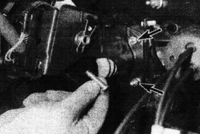
7. Working inside the car, remove the spring clip and remove the pin securing the booster pushrod to the brake pedal. Pay attention to the spacer gasket that is located on the inside of the pedal (see illustrations).
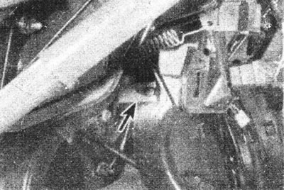


3.7a. Remove the spring clip (marked with an arrow)...
3.7a. Remove the spring clip (marked with an arrow)...


3.7b....then remove the pin securing the booster pushrod to the brake pedal; the amplifier mounting…

3.7b....then remove the pin securing the booster pushrod to the brake pedal; the amplifier mounting nuts are marked with arrows


8. Remove the four nuts and washers securing the booster to the engine compartment bulkhead. Return to the engine bay and remove the booster, taking note of the gasket installed on the back of the block.

Installation


9. Before installation, make sure the booster pushrod length is adjusted correctly. To do this, remove the gasket and take the measurements shown in the figure (see illustration).
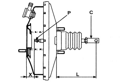
3.9. Adjusting the length of the booster push rod: C - Push rod fork; L - 110 mm; R - Push rod nut;…

3.9. Adjusting the length of the booster push rod: C - Push rod fork; L - 110 mm; R - Push rod nut; X - 22.3 mm.


If adjustment is necessary, change the length "L" by loosening the lock nut and moving the push rod fork in the desired direction. To change the "X" distance, move the "P" nut. After adjusting, ensure the fork locknut is tight.

10. Inspect the check valve O-ring for damage and replace it if necessary.

11. Install a new gasket on the rear of the amplifier and install the unit into the engine compartment.

12. When working inside the car, make sure that the booster pushrod is properly connected to the brake pedal. Install the booster mounting nuts/washers and tighten them to the torque specified in the Specifications.

13. Place the spacer on the inside of the pedal. Install the pushrod pin and secure it with the spring clip.

14. Install the expansion tank into its bracket and secure it with a rubber belt.

15. Connect the vacuum hose to the booster check valve and securely tighten its mounting clamp.

16. Install the master cylinder (see Chapter 8).

17. Finally, start the engine and check the vacuum hose connection to the booster for leaks. Check the operation of the amplifier as described at the beginning of this Chapter.
This article is available on: russian, bulgarian, belarusian, ukrainian, serbian, croatian, romanian, polish, slovak, hungarian
Article has been reviewed by editor: Fedoseev Denis
Share with friends:
Previous
Clio 1: Brake system
Next

Brake pedal — removal and installation
General description of the braking system
Brake system specifications
Vacuum booster control valve — removal, inspection and installation
Vacuum Booster Air Filter Replacement
Brake hydraulic system — bleeding
Brake pipes and hoses — replacement
Master cylinder — removal and installation
Other articles on other Renault models

➽ Removal, checking and installation the one-way valve of the… Renault Megane 1 (1995-2002)
➽ Checking the operation of the brake booster check valve Renault Fluence 1 (2009-2020, petrol)
➽ Checking the operation of the brake booster Renault Logan 1 (2004-2012, petrol)
➽ Checking the operation of the brake booster Renault Sandero 1 (2007-2012, petrol)
➽ Vacuum brake booster Renault Duster 1 (2009-2017)
Link to this article in different formats
Reviews and comments of visitors
No comments yet


Add two numbers 47 + 42


Clio 1 (1990-1998) 
  • General information
  • Maintenance
  • Troubleshooting
  • Power unit
  • Petrol engines 1.1 l (C)
  • Petrol engines 1.2 l (D)
  • Petrol engines 1.2/1.4 l (E)
  • Petrol engines 1.8 l (F)
  • Diesel engines
  • Overhaul of engines
  • Cooling and heating
  • Fuel system (carburetor)
  • Central fuel injection
  • Distributed fuel injection
  • Fuel system (diesel)
  • Starting and charging system
  • Ignition system (transistor)
  • Ignition system (electronic)
  • Pre-heating of diesel engines
  • Transmission
  • Clutch
  • Manual gearbox
  • Automatic gearbox
  • Drive shafts
  • Chassis, running gear
  • Brake system
  • Car suspension
  • Steering system
  • Body and interior
  • Exterior (external elements)
  • Doors, locks and windows
  • Electrical equipment
  • Equipment and devices
  • Electrical circuits
RenaultBook.ru © 2018–2026 | Mobile version | News and articles | Sitemap: EN BG BY UA RS HR RO PL SK HU | Administration | Site search | Bookmark
Duster 1 (2009-2017) | Fluence 1 (2009-2020, petrol) | Kangoo 1 (1997-2007) | Laguna 2 (2001-2007) | Logan 1 (2004-2012, petrol) | Logan 2 (2012-2020) | Megane 1 (1995-2002) | Megan 2 (2002-2009, petrol) | Sandero 1 (2007-2012, petrol) | Scenic 1 (1996-2003) | Symbol 1 (1999-2008, petrol) | Symbol 2 (2008-2013, petrol) | Renault 19 (1988-1996) | Espace I and II (1984-1996) | Espace III (1996-2002) | Clio 1 (1990-1998) |
We want your visit to be comfortable 😌 and use cookies 🍪 to do so.