



Intermediate shaft engines
Removal
1. Remove the tray as described in Chapter 10.
2. Unscrew the four pump mounting bolts and separate the pump from the cylinder block and drive gear (see illustration).
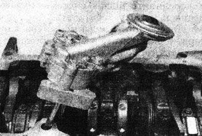
11.2. Removing the oil pump.
3. If necessary, remove the two mounting bolts and remove the oil pump drive gear cover and O-ring from the rear of the cylinder block. Remove the drive gear from the block. Discard the O-ring.
Inspection
4. Unscrew the mounting bolts and remove the pump cover. Remove the idler gear and pinion gear/shaft. Mark the idler gear so it can be installed in the same position.
5. Remove the mounting bracket and remove the support cup, spring, spring seat and plunger of the pressure reducing oil valve.
6. Clean the components and carefully inspect their condition. Replace the pump assembly if excessive wear is present (there are no spare parts for sale).
7. If the components appear to be serviceable, measure the clearance between the pump housing and the gears using feeler gauges. Also measure the axial clearance of the gears and check the flatness of the end cover (see illustrations).
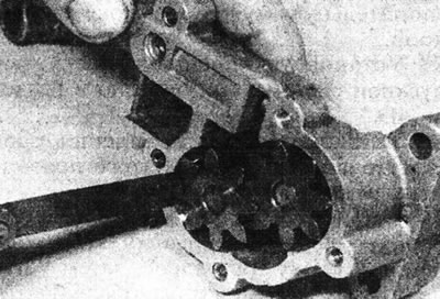
11.7a. Measuring the gap between the gear and the oil pump housing.
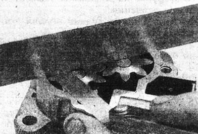
11.7b. Measuring the axial clearance of the oil pump gear.
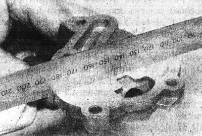
11.7s. Checking the flatness of the oil pump cover.
If the gaps exceed those specified in Specifications permissible deviations, the pump must be replaced.
8. If the pump condition is satisfactory, reassemble the components in reverse order of disassembly. Fill the pump with oil, then install the cover and tighten the bolts securely.
Installation
9. Where necessary, install the pump drive gear into the cylinder block, properly engaging it with the intermediate shaft. Install the pinion cover using a new O-ring and tighten the mounting bolts securely.
10. Wipe the mating surfaces of the oil pump and cylinder block.
11. Check that the locating pin is in the oil pump, then place the pump in the operating position. Engage the pump drive shaft with the drive gear slots. Install the pump mounting bolts and tighten them to the specified tightening torque Specifications.
12. Install the tray as described in Chapter 10.
Engines without intermediate shaft
Removal
13. To remove only the oil pump, first remove the oil pan, see Chapter 10.
14. Remove the two mounting bolts and remove the oil pump, tilting it to disengage the sprocket from the drive chain.
15. To remove the oil pump together with the drive chain and sprocket, first remove the oil pan (Chapter 10), then unscrew the crankshaft oil seal housing from the drive belt side as described in Chapter 12. Note the chain guide and two mounting pins.
16. Remove the bolts securing the sprocket to the oil pump hub. Hold it with a screwdriver inserted through one of the holes.
17. Remove the drive sprocket from the crankshaft and the driven sprocket from the oil pump together with the chain. Please note that the drive sprocket does not have a key and is secured to the crankshaft only with a bolt. Therefore, it is very important to tighten the pulley bolt correctly, otherwise there is a possibility that the oil pump will not function.
18. Unscrew the oil pump as described in point 14 above.
Inspection
19. Proceed as described in points 4-8 above.
Installation
20. Wipe the contact surfaces of the oil pump and cylinder block.
21. Make sure the two locating pins are in place in the cylinder block, then position the oil pump on them and insert the two mounting bolts. Tighten the bolts securely.
22. Place the chain on the sprockets (if deleted), then install both sprockets with the chain on the crankshaft and on the oil pump hub.
23. Align the holes, then insert the bolts and tighten them, holding the sprocket still with a screwdriver.
24. Install the oil seal housing as described in Chapter 12 (don't forget the chain guide and two mounting pins) and a pallet (refer to Chapter 10).