



- Clamp - Sus. 1414-01
Tightening torques:
- Wheel bolt - 90 Nm
- Lever to subframe mounting nuts - 90 Nm
- Lever to hub mounting nut - 55 Nm
- Stabilizer mounting nuts - 15 Nm
Removal
- set the parking brake;
- raise the front of the vehicle, place safety supports under the body and remove the corresponding wheel;
- unscrew the bolts and unscrew the nuts securing the stabilizer to the suspension arm;
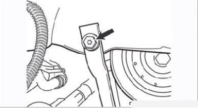
Figure 5.6. The arrow indicates the upper bolt for fastening the support bar
- if there is a support bar in the design, unscrew the bolts that secure it to the side member and to the front bolt of the lever axle (Figure 5.6 and 5.7) and remove the bar;
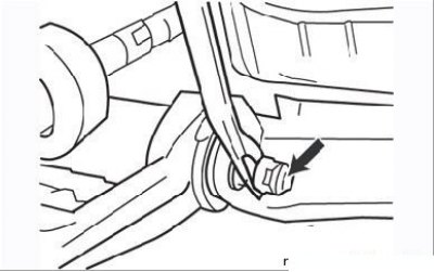
Figure 5.7. The arrow indicates the nut securing the lower part of the support bar
- unscrew the nut and remove the bolt of the clamp securing the lower ball joint to the steering knuckle;
- remove the support pin from the clamp, being careful not to damage the support and CV joint boots, as well as the plastic protective gasket of the joint;
- unscrew the axle nuts and bolts and remove the lever from the car;
- clean the lever from dirt and inspect it for deformations, cracks and other damage;
- the ball joint pin should move in the housing without jamming and should not have excessive wear, the cover should not have damage. If necessary, replace damaged parts.
Installation
- Check for the presence of the plastic protective washer (A) on the ball joint shaft of the control arm.
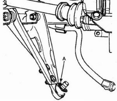
- Attach the control arm to the suspension bracket and secure it with the two axle bolts on the back of the control arm. Screw the nuts onto the bolts, tightening them by hand;
- Connect the lever to the hub and tighten the ball joint mounting nut.
- Install the stabilizer. Using the clamp Sus. 1414-01, compress the stabilizer bushing and tighten the fastening nut.
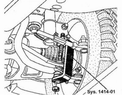
- lower the car onto its wheels, pump the suspension manually and tighten the threaded connections to the specified torques, starting with the axle nuts, then the stabilizer and support bar;
- check and adjust the front wheel alignment angles if necessary.
Replacing the lower control arm bushings
1. Using a mandrel (pipe cutting with a diameter of 30 mm) press out one of the two lever bushings.
2. Press in a new bushing so that the distance (A) between the bushings is 146.5 mm.
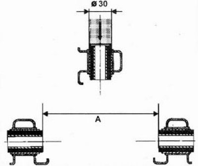
3. Using a mandrel, press out the second lever bushing.
4. Press in the new bushing so that the distance (A) between the bushings is 146.5 mm.
You can find the original at this link [RENAULTBOOK]