
Removing
Disconnect the wires from the battery terminals, starting with the negative terminal.
Remove the relay socket to gain access to the passenger compartment blower ECU.
Remove the air duct supplying air to the front left side of the passenger compartment.
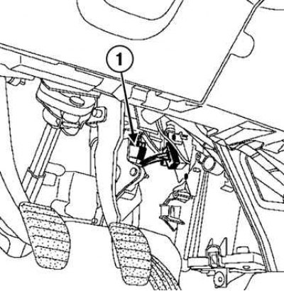
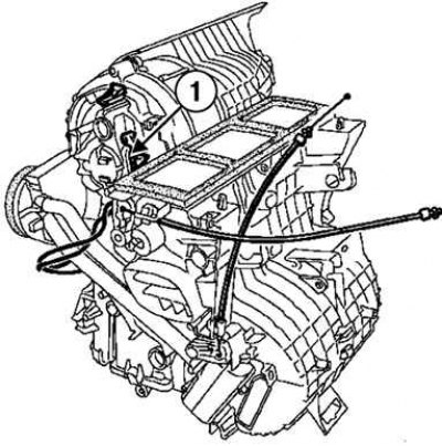
Pic. 8.145. Accelerator Pedal Position Sensor Connector: 1 - connector
Disconnect the accelerator pedal position sensor connector (pic. 8.145).
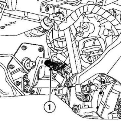
Pic. 8.146. Removing the brake light switch: 1 - brake light switch
Remove the brake light switch by turning it a quarter of a turn (pic. 8.146).
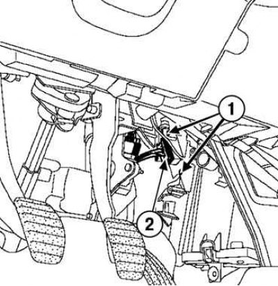
Pic. 8.147. Removing the Blower ECU Mounts: 1 - ECU mounting bolts; 2 - ECU connector
Remove the two bolts securing the passenger compartment blower ECU and disconnect the passenger compartment blower ECU connector (pic. 8.147).
Slightly spread the ECU mounting tabs.
Pic. 8.148. passenger compartment blower control unit
Remove the passenger compartment blower ECU (pic. 8.148).
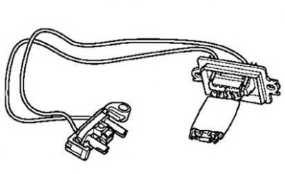
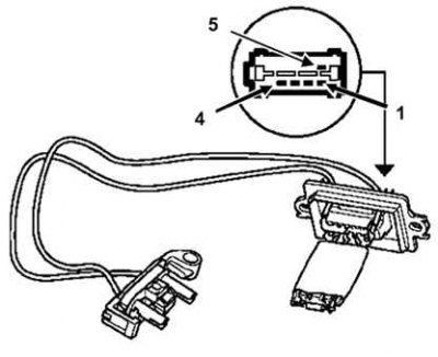
Pic. 8.149. Removing the wiring harness from the passenger compartment electric fan: 1 - block of wires
Remove the wiring harness from the passenger compartment electric fan (pic. 8.149).
Attention! Pull the stem to set the movable part of the switch to its original position.
Installation
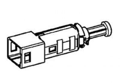
Pic. 8.150. Stoplight switch
Install the brake light switch (pic. 8.150).
Turn the brake light switch a quarter of a turn clockwise.
Installation is made in an order, the return to removal.
ECU connection
Pic. 8.151. ECU connection
See fig. 8.151
Table 8.4. Connecting the heater control panel
| Control panel contact | Purpose | Sensor or actuator contact |
| 1 | «Weight» | |
| 2 | switching on the 1st fan speed | Pin 1 of connector A of the resistor block |
| 3 | switching on the 2nd fan speed | Pin 2 of connector A of the resistor block |
| 4 | turning on the 3rd fan speed | Pin 3 of connector A of the resistor block |
| 5 | turning on the 4th fan speed | Pin 4 of connector A of the resistor block |
| 6 | Not used | |
| 7 | electric fan zero speed signal | CECBS |
| 8 | «+» after the ignition switch | |
| 9 | Request to turn on the heated rear window. | CECBS |
| 10 | Switch and signal lamp for heated rear window | CECBS |
| 11 | «Weight» | |
| 12 | air conditioning warning light signal | CECBS |
| 13 | request to turn on the air conditioner | CECBS |
| 14 | «+» after the ignition switch | |
| 15 | «+» side light | Instrument lighting dimmer |
Table 8.5. Assignment of the contacts of the heating ECU
| Contact | Purpose |
| 1 | Speed control 1 |
| 2 | Speed control 2 |
| 3 | Speed control 3 |
| 4 | «Weight» |
| 5 | Power supply |
Table 8.6. Assignment of the contacts of the heating ECU
| Enabled speed | Measurement contacts | Resistance, Ohm |
| Speed 1 | 1-4 | 5,2+0,5 |
| Speed 2 | 2-4 | 3,2±0,5 |
| Speed 3 | 3-4 | 2+0,5 |