



Contents: Coolant 🠛 Air conditioning system maintenance 🠛 Bactericidal preparation for air…🠛 Draining the refrigerant 🠛 Air pumping 🠛 Refrigerant charging 🠛 Leak detection 🠛
Coolant
The characteristics of the refrigerant are indicated on the label located in the engine compartment of the vehicle.
To collect, create a vacuum and charge R134A refrigerant, use the high pressure line of the charging station.
Note: Be sure to plug the air conditioning system piping openings with caps to prevent moisture from entering the system. Remove the caps from replacement parts only at the last moment before installing them.
Note: When the engine is running, check for leaks with a leak detector five minutes after refueling; in this case, the heater and air blower must operate at maximum mode.
Note: Follow all oil addition instructions carefully when working on air conditioning system components.
Note: When replacing valves, maintain the required tightening torque of 8 Nm.
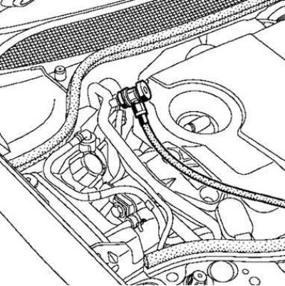
Fig. 8.135. Refrigerant charging
Air conditioning system maintenance
Each year of operation it is recommended:
- clean and blow out the condenser and radiator of the engine cooling system;
- make sure that the condensate drain hole in the cold air blower unit is not clogged.
It is recommended to check the refrigeration circuit charge with refrigerant or drain the refrigerant every four years.
Bactericidal preparation for air conditioning system treatment
Note: Treat the heating and ventilation system with a special preparation after each winter season or a long break in the system's operation to eliminate possible contamination.
Note: Spray the entire product from the aerosol can, equipped with an extension, through the filter pipe of the cabin ventilation system.
Attention! It is strictly forbidden to spray the preparation through the air intake and due to the risk of damage to the air injection electric fan.
Attention! Please wait 15 minutes.
Attention! Turn on the fan at very low speed for 5 minutes.
Draining the refrigerant
Note: Since the air conditioning system circuit is equipped with only one filling valve, some filling stations use only the high pressure line.
Note: In some cases, allow the system to run for a few minutes before draining the refrigerant to ensure complete drainage.
When draining the refrigerant or checking the charge of the refrigeration circuit, three cases must be taken into account:
- 1. The engine and air conditioner are working;
- 2. The engine is running, but the air conditioner is not working;
- 3. The engine and air conditioner do not work.
The engine and air conditioner are working
Let the air conditioner run until the engine cooling fan turns on twice, then stop the engine.
Perform the first refrigerant drain (measure the amount drained), wait 15 minutes.
Check that the relative pressure is below or equal to 0 bar, resume drain cycles if the pressure is not below or equal to 0 bar.
Sum the amount of refrigerant drained in all cycles.
The charge is considered sufficient if the resulting amount is +35 g or –100 g from the nominal value.
The engine is running but the air conditioning is not working
Let the engine run until the electric cooling fan turns on twice, then stop the engine.
Perform the first refrigerant drain (measure the amount drained), wait 15 minutes.
Let the engine run until the electric cooling fan turns on twice, drain the coolant a second time (measure the amount drained).
Resume drain cycles if pressure is not below or equal to 0 bar.
Sum the amounts of refrigerant drained in all cycles.
The charge is considered sufficient if the resulting amount is +35 g or –100 g from the nominal value.
The engine and air conditioner do not work
Perform the first refrigerant drain (3. The engine and air conditioner do not work.), wait 2 hours.
Resume drain cycles if pressure is not below or equal to 0 bar.
Sum the amounts of refrigerant drained in all cycles.
The charge is considered sufficient if the resulting amount is +35 g or –100 g from the nominal value.
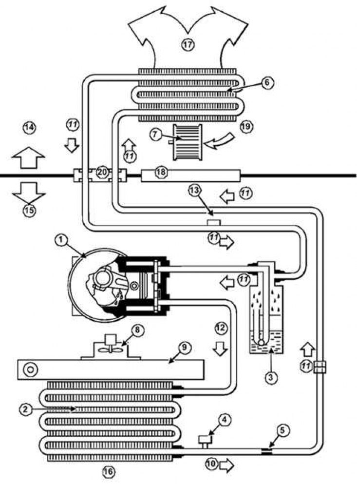
Fig. 8.136. Operation of the air conditioning system: 1 – compressor; 2 – condenser; 3 – receiver-dryer; 4 – pressure sensor; 5 – reducer with tubular regulating valve; 6 – evaporator; 7 – electric cabin fan; 8 – electric fan of the engine cooling system; 9 – engine cooling system radiator; 10 – high pressure refrigerant; 11 – low pressure steam; 12 – high pressure steam; 13 – filling valve; 14 – salon; 15 – engine compartment; 16 – outside air; 17 – to the air distribution unit; 18 – front shield; 19 – outside or recirculated air; 20 – flange of pipelines on the front shield
Air pumping
Be sure to thoroughly evacuate the air from the refrigeration circuit before charging it with refrigerant, otherwise the air conditioner will fail.
There are two cases to consider:
- air is pumped out immediately after the circuit is discharged;
- air is pumped out several hours or days after the circuit is discharged.
Air is pumped out immediately after the circuit is discharged.
Air is pumped out for 20 minutes.
Air is pumped out several hours or days after the circuit is discharged.
Air is pumped out for 45 minutes to completely remove traces of moisture.
After the air has been pumped out, check the circuit for leaks (some charging stations do this automatically).
Refrigerant charging
Add oil of the required grade and in the required quantity depending on the work performed.
Perform the refueling.
Empty the filling station lines.
Check the system for functionality. Search for leaks.
Leak detection
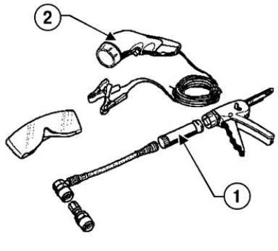
Fig. 8.137. Refrigerant leak detection tool: 1 – capsule; 2 – ultraviolet lamp
To find leaks, a contrast agent is used, supplied in single-use capsules, and traces of leaks are detected using an ultraviolet lamp (fig. 8.137).
The contrast agent remains in the air conditioning system.
Using an ultraviolet lamp, you can check the condition of the refrigeration circuit.
Attention! If there are characteristic fluorescent traces, it is prohibited to introduce contrast agent into the refrigeration circuit.
Caution! Administer a dose of contrast agent if there are no characteristic fluorescent traces or warning label (about past use of contrast agent).
Introduction of contrast agent into the contour.
Install the contrast injection system on the low pressure valve, 3a on vehicles with a single valve.
Inject contrast agent into the contour.
Turn on the air conditioner and let it run for about 15 minutes.
(Original article is on the portal www.renaultbook.ru)
Leak detection procedure.
Perform a preliminary check (with the engine not running), by passing a beam of ultraviolet lamp along the refrigeration circuit.
If no leaks are detected:
- thoroughly clean the outer surfaces of the refrigeration circuit components,
- turn on the air conditioner compressor and do not turn it off until the refrigerant leak is located (if unsuccessful, check the condition of the evaporator).
Attention! After using a contrast agent, be sure to indicate on the warning label (supplied with the capsule of this substance) the fact of its use and the date of the operation. The label should be pasted in a visible place near the filling valves of the refrigeration circuit (on the shock absorber support cup).
Table 8.3. Localization of refrigerant leaks
| Place of application | Detection Zone |
| Condenser | At the entrance and exit |
| Evaporator | Connecting flange |
| Compressor | At the entrance and exit |
| Receiver-dryer | At the entrance and exit |