
Removal
- Remove the gearbox.
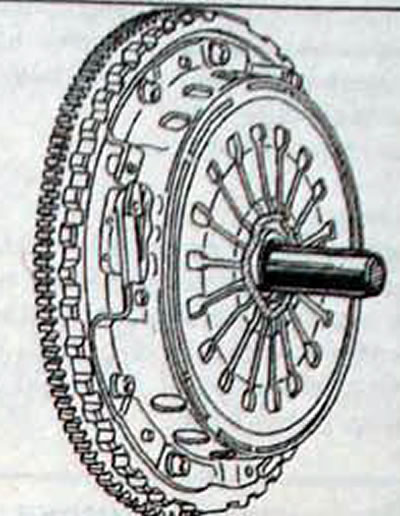
- Use tool Mot.852 or a large screwdriver to hold the teeth of the ring gear and block the flywheel from turning (pic. 5.2, 5.3).
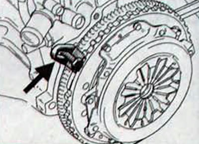
Pic. 5.2. Using tool Mot.852 to prevent the flywheel of a gasoline engine from turning
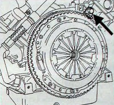
Pic. 5.3. Using tool Mot.852 to secure the flywheel of a diesel engine from turning
- Gradually loosen the clutch assembly mounting bolts diagonally, turning each bolt half a turn until. until the spring action stops and the bolts can be unscrewed by hand. This releases the clutch driven disc.
- Mark the position of the clutch housing in relation to the flywheel.
- Unscrew the bolts securing the clutch housing to the flywheel and remove the housing assembly with the pressure plate.
- Remove the clutch driven disc.
Examination
- Check the condition of the flywheel friction surface for cracks, burns and surface wear.
- Check flywheel runout. Install a bracket with a dial-type indicator on the engine cylinder block so that the measuring tip of the indicator rests against the end of the flywheel. Set the indicator to 0. Turn the engine crankshaft and record the maximum and minimum values on the indicator.
- Check the condition of the clutch pressure plate.
- Check the reliability of the spring connection between the pressure plate and the housing of the clutch drive part. Scratches and missing or damaged rivets are not allowed.
- Check the pressure plate for cracks, burns and surface wear. Using a steel ruler and feeler blade, check the flatness of the pressure plate working surface. Check the condition of the friction linings of the driven clutch disc and if there are traces of oil or mechanical damage on them, replace the driven disc.
- Check the thickness of the clutch disc lining.
- Check that the springs are not broken or cracked. Check the condition of the splines in the clutch disc hub for wear. The clutch driven disc should slide easily and smoothly on the splines of the gearbox input shaft. If the clutch driven disc is replaced, the clutch release bearing must also be replaced. Check the condition of the clutch release bearing, which should rotate easily, evenly and quietly and there should be no play in it. The working surface of the bearing acting on the pressure spring must be smooth, without cracks or wear.
- A faulty clutch release bearing can be determined without removing it from the car, for which you need to press the clutch pedal while the engine is running. If noise occurs when you press the clutch pedal, the clutch release bearing is faulty and needs to be replaced.
- Check for traces of oil in the crankshaft rear oil seal area.
Installation
Cars with petrol engines
- Clutch repair kit contains bushing (bearing simulator), which is used to center the driven disk.
- When installing a new driven disk and clutch pressure plate, remove the anti-corrosion protection from them.
- Remove grease from the crankshaft flange bore under the bushing.
- Apply Loctite Frenbloc to the outer diameter of the bushing.
- Using a piece of pipe with an outer diameter of 38 mm, install the bushing until it stops in the hole in the crankshaft flange.
- Pay attention to the position of the bushing when installing and make sure the bushing is installed correctly (pic. 5.4).
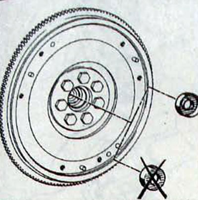
Pic. 5.4. Direction of installation of the bushing at the end of the crankshaft
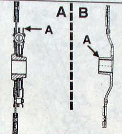
Pic. 5.5. Hub lug location (A), which when installing the clutch driven disc should be directed towards the flywheel: A - gasoline engines; B - diesel engines
Note. The driven disc hubs are nickel plated and do not require lubrication.
- Be careful when installing the driven disk. so that oil does not get on its friction linings even in small quantities. Therefore, before installation, wipe the contact surface of the flywheel and the surface of the pressure plate with a clean rag, and install the driven disk with clean hands.
- Install the clutch driven disc with the centering mandrel using the hub protrusion «A», directed towards the pressure plate.
- To install the driven disk, use the included plastic centering mandrel (pic. 5.6).
Pic. 5.6. Using a plastic mandrel to center the clutch disc
Cars with diesel engines
- Clean the gearbox input shaft splines and install the clutch without lubrication.
- Degrease the surface of the flywheel under the clutch driven disc and the friction linings of the driven disc.
- Install the driven disk with the protrusion (A, fig. 5.5) the hub must be on the flywheel side.
- Use the centering mandrel included in the repair kit.
All cars
- Install the clutch housing and pressure plate assembly. When reinstalling a previously removed clutch pressure plate, check that the marks made before removal are aligned.
- Gradually tighten the clutch housing bolts in a diagonal sequence.
- Remove tool Mot. 582, blocking the flywheel from turning
- Lubricate the hole in the clutch release bearing with MOLYKOTE BR2 grease. as well as the bearing guide sleeve, the clutch release fork legs and its ball joint.
- On vehicles with gasoline engines, after connecting the gearbox, set the gear sector of the wear compensation mechanism to the working position and check the correct operation of the automatic wear compensation mechanism.
- On cars with gasoline engines, check the travel of the clutch release fork, which should be within 26-28 mm (pic. 5.7).
- On vehicles with diesel engines, apply MOLYKOTE BR2 grease to the guide bushing and clutch release fork tabs. Position the clutch release bearing on the guide sleeve and the clutch release fork tabs on the clutch release bearing.
- Install the gearbox.
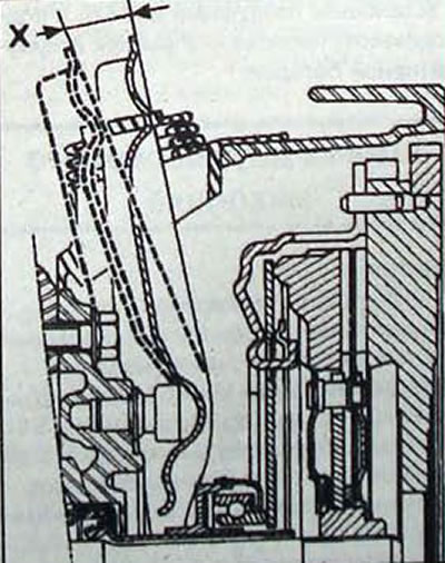
Pic. 5.7. Place for measuring the clutch release fork stroke: X = 26-28 mm
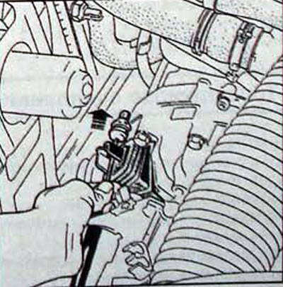
Pic. 5.8. Checking the free play of the clutch cable on cars with gasoline engines
Note. On cars with gasoline engines, with the clutch pedal released, removing the clutch cable from the fork side, check the free play, which should be 3 mm.