
Attention
- The ball joint can only be replaced once, after which the lower front suspension arm must be replaced. Ball joints supplied as spare parts have an identification mark (cutout on the supporting surface). A ball joint without a mark is a standard part and can be replaced.
- The cutout ball joint is a replacement part and cannot be re-replaced, but requires replacement of the arm assembly.
Removal
- Disconnect the cable from the negative terminal of the battery.
- Raise the car on a lift and remove the Wheel from the required side.
- Using the Tav puller. 476 disconnect the tie rod end from the steering knuckle (rice. 10.7).
- Remove the floating brake caliper bracket and secure it to the suspension spring to protect the brake hose from damage.
- Install the protective cover on the bellows of the drive shaft outer joint
- Loosen the lower ball joint pin fastening nut as much as possible and use a ball joint puller to press the joint out of the steering knuckle (rice. 10.8).
- Remove the bolts securing the shock absorber strut to the steering knuckle.
- Disconnect the steering knuckle from the shock absorber strut, move the knuckle assembly with the drive shaft to the side and hang it to the body.
- Use tool T.AV 1261 to press the ball joint out of the lower arm (pic. 10.14).
- To install the ball joint, insert the washer (A, fig. 10.15) and spacer ring (IN) in the device T. Av. 1261-01
- To install the ball joint, use tool T. Av. 1261.
- Further installation is carried out in the reverse order of removal.
- Press the brake pedal several times to press the brake pads against the brake rotor.
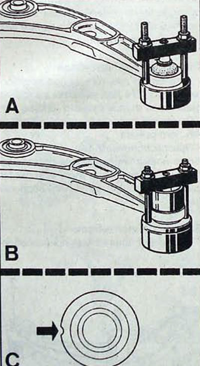
Pic. 10.14. Replacement of the ball joint of the lower arm of the front suspension: A - use of the T.AV device. 1261 for squeezing the ball joint out of the lever; B - use of device T. AV.1261 for pressing the ball joint into the lever; C - location of the ball joint identification mark
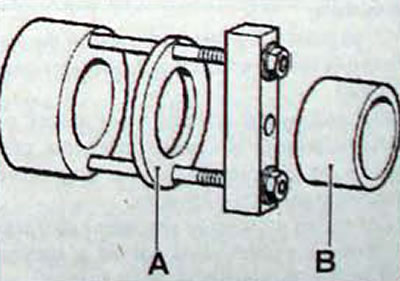
Pic. 10.15. Device T. Av. 1261-01 for installing the ball joint: A - washer; B - spacer ring
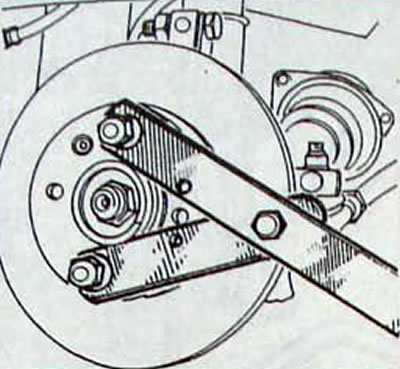
Pic. 10.16. Using a special device Rou. 604-01 for blocking the hub from turning
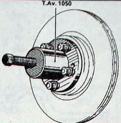
Pic. 10.17. Using the puller T. Av. 1050 for pressing the drive shaft out of the front wheel hub
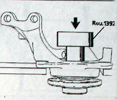
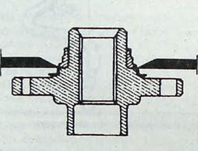
Pic. 10.18. Using the Rou device. 1392 for pressing the hub out of the steering knuckle
Pic. 10.19. Installing the puller jaws to remove the inner bearing race from the front wheel hub