
2. Use a winch to remove. In addition, you will need a tie rod joint puller, a suitable punch to knock out the pins from the input shaft connections, and two struts that fit under the front wheel suspension. If there are no racks, use two wooden decks.
Models with 4-cylinder engine
Removing
3. Disconnect the negative cable from the battery. Disconnect the clutch pedal cable from the clutch release lever (see illustration).
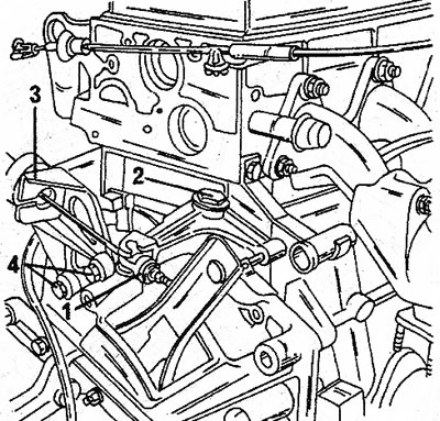
2.3 On earlier models, the clutch pedal cable is connected at the indicated location, on later models - see illustration 5.17 in Section 61. Fastening the cable to the clutch release lever; 2. Middle bolt; 3. Rope support; 4. Support bolts
4. Remove the wheel nuts and axle shafts, place the front of the vehicle on stands and remove both front wheels.
5. Disconnect a reception pipe from a final collector.
6. Install both props (see illustration) between the lower shock absorber bolt and the independent wheel suspension arm bearing shaft on both sides. These mounts are installed to support the front suspension while the shafts are removed.
2.6 Install supports under the front suspension
7. Place a suitable container under the gearbox and drain the gear oil. After the oil is completely glass, wrap the drain plug. When draining the oil, keep the filler plug open so that the oil can drain better.
8. Remove both disc brake calipers without pinching the brake hoses. Secure the calipers with wire so they don't hang from the hoses.
9. Remove the transmission drive shafts as described below.
10. Remove the tie rod joint nut and disconnect the joint with a puller from the steering link arm.
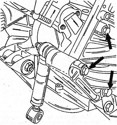
11. In the same way disconnect the top hinge of a drive of the cross-section lever of a suspension bracket from a rotary fist. Then press the steering knuckle down and at the same time remove the drive shaft from the gearbox. Do this work on both sides of the car (see illustration).
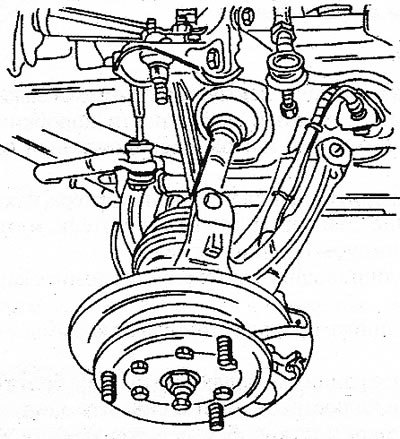
2.11 Pull the steering knuckle out and press down to disengage the axle shafts
12. Disconnect from the plug wiring of the switch of lanterns of a backing and remove a spiral of a speedometer. It is held by a spring loaded pin.
13. Disconnect the gear selector (see illustration).
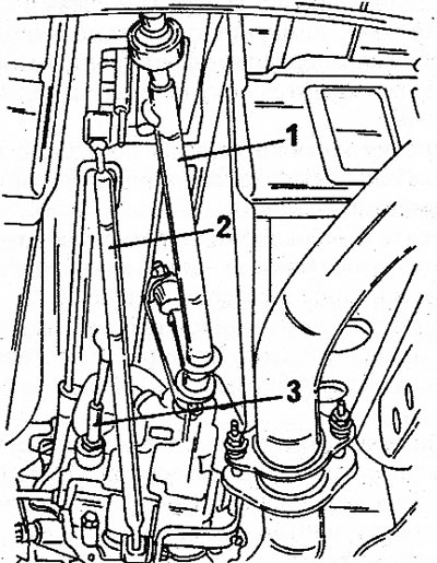
2.13 Remove the gear change mechanism; thrust (3) installed since 1987 1. Gear selector rod; 2. Thrust of the choice of the forward course; 3. Reverse selection rod
14. Remove the electronic ignition system sensor.
15. Remove from the bottom surface of a transmission a safety guard located under coupling.
16. Disconnect the crankcase ventilation hose located at the end of the double muffler pipe and unscrew the pipe from the bottom of the body.
17. At the all-wheel drive car remove cardan shaft.
18. Disconnect the starter wires from the terminal and remove the starter.
19. On earlier models, remove both bolts (designation 4 in illustration 2.3) and remove the support.
20. Jack up the gearbox (place a piece of wood between the jack head and gearbox) and remove all bolts connecting the engine and gearbox.
21. Disconnect the suspensions on the right and left and remove the gearbox from the jack, carefully disengaging the gearbox input shaft from the clutch friction disc. Do not let the block hang on the shaft.
Installation
22. Install the gearbox in the reverse order, paying attention to the points below.
23. Apply a small amount of graphite grease to the transmission input shaft gears. Also lubricate both axle gears.
24. Be convinced that both adjusting plugs are in the bottom half of the block of cylinders; otherwise, pull them out of the gearbox and hammer them into the cylinder block.
25. Using a jack, set the gearbox in the proper position and bring the input shaft of the gearbox into engagement with the friction disc. Push the gearbox firmly against the engine. While doing this, support the clutch release lever as the release bearing may fall off the fork. Tighten the bolts in a circular sequence.
26. Establish suspensions of a transmission.
2.26 Connection between drive shafts and differential side gears
27. Align the holes of the drive shafts and side gears of the differential, then slide the shafts into the gearbox, at the same time raise the steering knuckle and press it inward. Use a suitable punch to align the holes (see illustration) and drive in a new pin. Lubricate the ends of the pins with sealant.
28. Install both hinges. If the bolts turn with the ball head, insert a screwdriver into the connection when removing the nut. Always use a new nut. tightening torque see Specifications.
29. When installing disc brake calipers, lubricate the mounting bolts with sealant.
30. If necessary, adjust the clutch clearance. Otherwise, check the functioning of the adjusting mechanism.
31. When installing the exhaust pipe on a rubber support, do not put an insulating washer between the metal-elastic bearing and the pipe bracket.
32. Fill in gear oil. Do not overfill.
Models with V6 engine
Removing
33. If the gearbox will be removed at a workshop, assemble the front exhaust pipe with a coupler for later installation. When carrying out repair work yourself, it is recommended to remove the exhaust system completely in order to provide enough space for removing the gearbox. The process of removing the gearbox is carried out in the same way as for cars with a 4-cylinder engine, taking into account the following features.
34. Disconnect the clutch slave cylinder hydraulic line. The connection is located next to the air intake housing (signed at the top «V6 Injection»).
35. Turn away bolts of a starter and remove a starter. The safety guard is located behind the starter.
36. Remove brackets and engine mounts (see illustration). The top bolt is the connection between the engine and gearbox. This bolt is shorter than the others.
2.36 Engine brackets and mounting brackets are attached with bolts shown
37. Jack up the gearbox and remove the bolts connecting the engine to the gearbox. Remove the gearbox, but do not let it hang on the input shaft.
Installation
38. Install in reverse order. Bleed the clutch system after installation. The bleed valve is located near the front of the gearbox (left).