
Removing
1. The clutch cannot be replaced without removing the engine and transmission. Remove each unit in the appropriate manner. Follow the directions below.
2. Mark the mounting position of the clutch in relation to the flywheel. To do this, use the core.
3. Loosen the six clutch bolts in diagonal sequence to relieve diaphragm spring pressure. To do this, block the flywheel properly.
4. Remove the clutch and remove the friction disc. If the clutch is hanging on the flywheel dowel pins, carefully pry it out with a screwdriver. Note that the more protruding side of the friction disc hub points towards the gearbox, i.e. out.
5. Immediately wipe the inside of the flywheel with a rag and inspect its rubbing surface. If the friction disc is worn down to the rivet heads, the flywheel surface may be damaged. If the engine separates from the gearbox, the clutch must always be disengaged.
Bulkhead
6. Check pressure plate and cover for damage or wear. If so, replace both components as a set.
7. Inspect for wear on the spring and friction disc hub. Since oily friction linings cannot be cleaned, the friction disc will have to be replaced.
8. Damper springs of friction discs have different colors. Measure the thickness of the friction linings. If it is less than 0.30 mm or soon reaches the wear limit, replace the disc.
9. To measure the runout of the friction disc, place it on a suitable punch mounted on the lathe
10. Install the dial micrometer on the special holder so that the measuring finger touches the edge of the disc (see illustration).
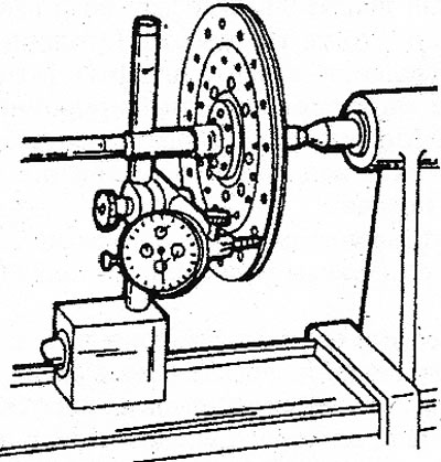
3.10 Measure friction disc runout
11. Slowly turn the dial and look at the micrometer reading. If the value is greater than 0.4 mm, the disc can be leveled if desired by gently tapping it with a mallet. Otherwise, replace the disk.
12. Make sure the friction disc hub is free to ride on the slots in the transmission input shaft.
13. If the runout is greater than 0.4 mm, the shaft gears are worn out. The reason for this is mostly the friction disc.
14. Inspect the inner surfaces of the compression spring sectors for wear. If deep wear marks are observed, completely replace the clutch.
15. The petals of the pressure spring should be in the same plane within 0.5 mm at the top. Deformed petals must be leveled with a special tool.
16. Place the measuring ruler on the rubbing surface of the pressure plate (see illustration) and measure the clearance with a feeler gauge. If the gap exceeds 0.3 mm, replace the clutch.
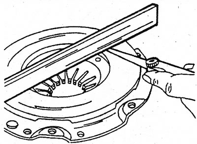
3.16 Check the inner surface of the pressure plate for wear
Installation
17. Install in reverse order, paying attention to the following:
- A) If the same clutch is installed, consider the marks made during removal. The new clutch can be oriented as you like.
- b) The centering of the friction disc is done by eye.
- With) Tighten the mounting bolts evenly in diagonal sequence to 25 Nm. The flywheel must be locked.
- d) Connect the gearbox to the engine and install the power unit on the car.