



Speed sensors
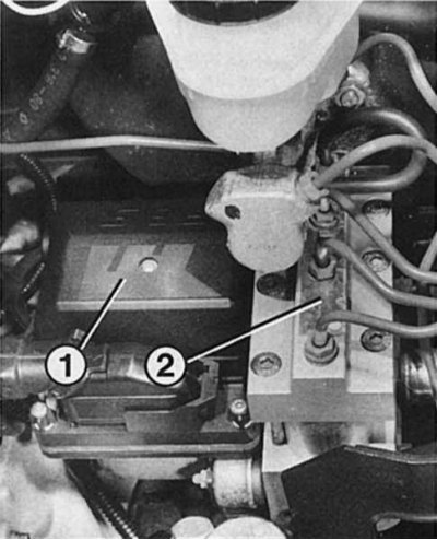
The hydraulic unit is located under the master brake cylinder.
1 — Electric pump casing, its relay and electromagnetic valve block;
2 — Valve block with electromagnetic valves and brake lines to the wheels.
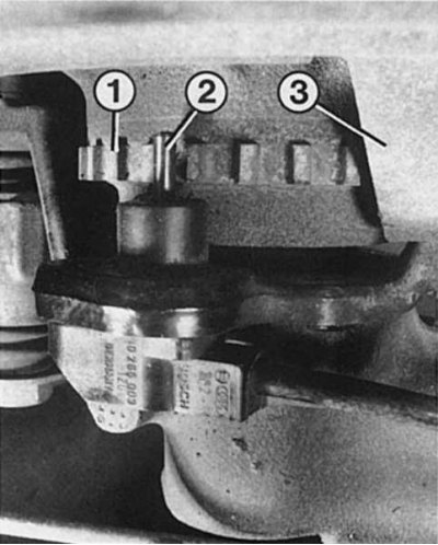
The figure shows the rear wheel speed sensor (2), located horizontally at a precisely calculated distance from the pulse wheel (1), which rotates behind the reflector (3) of the disc brake.
Each of the four speed sensors in the front and rear wheels reads the speed of the corresponding wheel and sends this information to the electronic control unit. Based on the signals processed there, the hydraulic unit is controlled.
The speed sensors are mounted on the wheels at a small distance from a special toothed - pulse wheel. The pulse wheel, rigidly connected to the hub, rotates in front of the speed sensor, depending on the speed of rotation of the wheel. The sensor consists of a magnetic core and a coil. Each tooth of the pulse wheel that passes in front of the sensor causes a short-term increase in voltage in the speed sensor. Thus, a change in voltage occurs in the sensor, which, depending on the frequency of rotation of the wheel, changes its frequency.
ABS control unit
The ABS control unit is located in the hydraulic unit and processes the speed data from the speed sensors. This data - about 8,000 per second at a speed of about 130 km/h - is compared with programmed values. If the control unit, based on the information about the different speeds, recognizes the risk of wheel locking, it "orders" the hydraulic unit to reduce the brake pressure to the point where the wheels do not lock.
View the original on the specified resource: RENAULTBOOK
The pressure reduction in the brake drive eliminates the risk of wheel locking, the control unit registers the change in information about the wheel speed and thus continuously regulates the pressure in the brake drive via the hydraulic unit. Such a change in the control signals coming into the hydraulic unit occurs depending on the state of the roadway during the entire braking process with a period of one millisecond. If the speed is less than 7 km/h, the ABS does not work.
Hydraulic unit
The main element of the ABS is the hydraulic unit located in the engine compartment, on the left in front of the main brake cylinder. It includes:
- Electric pump;
- Valve block with electromagnetic valves for regulating the pressure in the brake drive when there is a risk of wheel locking.
- When you press the brake pedal, the pressure through the valve block, via a pipeline specific to each wheel, is transmitted to one front wheel and the rear wheel located diagonally from it.
The brake fluid, which is supplied by the master brake cylinder through the valve block to the wheels, flows directly from the valve block back into the reservoir when the braking pressure drops. If the pressure in the brake drive increases again, the required amount of brake fluid flows again from the reservoir through the hydraulic pump directly into the corresponding brake drive circuit. You notice this due to the pulsation of the pedal, which begins when the pump and, accordingly, the ABS itself is operating.
Relay
To ensure the operation of the electromagnetic valves and the electric pump, one relay is installed under the cover of the hydraulic unit, each of which is protected by a 15 A fuse in the box under the instrument panel.