



Note: A new valve cover gasket will be required during installation.
Removal
1. Disconnect both cables from the battery (start with the negative).
2. Drain the cooling system, including the cylinder block, as described in Section 1. The block drain plug is located on the right rear surface of the engine, below the intake manifold. It is important that the fluid is drained from the block to prevent coolant from entering the pan.
3. Drain the engine oil as described in Section 1.
4. Remove the toothed drive belt, see Chapter 5.
5. If necessary, remove the air filter as described in Section 4B.
6. Disconnect the wires from the following components:
- Coolant temperature gauge sensor.
- Throttle body block.
- Ignition module.
7. Disconnect the gas pedal cable as described in Section 4B. Move the cable to the side.
8. If necessary, the intake and exhaust manifolds can be removed at this stage. Otherwise, disconnect the various fuel, vacuum and coolant hoses and electrical wiring from the throttle body and intake manifold (see Section 4B). Also disconnect the exhaust outlet pipe.
9. Loosen the clamps and disconnect the following hoses:
- Expansion tank hose from the cylinder head outlet.
- Upper radiator hose from thermostat housing.
- Crankcase ventilation hoses from the valve cover.
10. Disconnect the high tension wires from the spark plugs and carefully remove them from the holder on the valve cover. Unscrew the bolts and remove the holder.
11. Unscrew the valve cover from the cylinder head and remove the gasket (see illustrations).
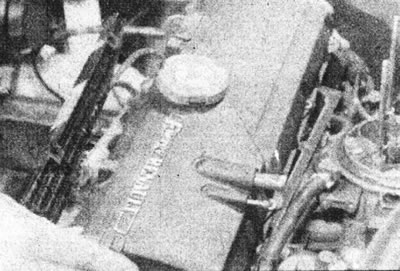
9.11a. Remove the valve cover...
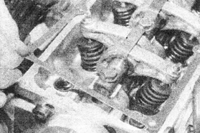
9.11b....and the gasket.
12. Remove the thermostat as described in Section 3.
13. Gradually loosen the cylinder head mounting bolts in the reverse order to that shown in Illustration 9.26a. Remove all bolts except the one located in the front right corner, which only needs to be loosened by three to four turns.
14. Now it is necessary to break the connection between the cylinder head, gasket and cylinder block, but it is important not to lift or disturb the cylinder liners. To do this, pull the left end of the cylinder head forward, rotating it around the remaining bolt, then move the head back to its original position. Failure to perform this procedure will result in cylinder liner movement and seal failure, resulting in leaks after head installation.
15. Remove the remaining bolt and lift the head off the cylinder block, then remove the gasket. Note the locating pin on the front right corner of the block (see illustrations).
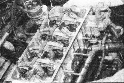
9.15a. Lift the head from the cylinder block.
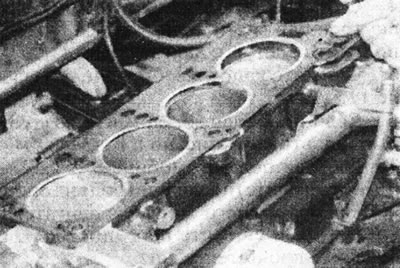
9.15b. Remove the cylinder head gasket.
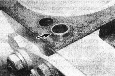
9.15s. Cylinder head alignment pin (marked with an arrow).
16. Please note that the crankshaft should not rotate with the head removed, as the liners may become displaced. If there is a need to rotate the crankshaft (for example when cleaning the piston head), secure the sleeves with bolts and washers or mounting clamps (see illustration).
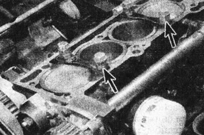
9.16. Clamps (marked with arrows), holding the cylinder liners in working position.
Inspection
17. The mating surfaces of the cylinder head and block must be completely clean. Using a scraper, remove all traces of gasket and carbon deposits and clean the tops of the pistons. Work especially carefully with the aluminum cylinder head, as the soft metal can be easily damaged. Also, be careful not to let dirt get into the oil and water passages - this is especially important for the lubrication chain, as carbon deposits can block the oil supply to the camshaft and crankshaft bearings or rocker arms. Use masking tape and paper to seal the water and oil passages and bolt holes in the cylinder block. Clean the piston heads in a similar manner.
18. Check the block and head for nicks, deep scratches and other damage. If there are small scratches, they can be carefully removed with a file. More serious damage can be repaired by resharpening, but this work should be entrusted to a specialist.
19. Using a ruler placed on its edge, check the warpage of the cylinder head. Also check the cylinder liner protrusion. These parameters are closely related to the burnout of the cylinder head gasket. See details. in Part F of this Section.
20. Clean all bolt holes in the block (see illustration).
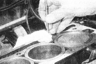
9.20. Clean the holes for the mounting bolts in the cylinder block.
Make sure there is no oil left in them, otherwise there is a risk that the block may crack under hydraulic pressure when tightening the bolts.
21. Inspect the bolt threads and the threads in the cylinder block for damage. If necessary, use a tap of the appropriate size to renew the threads in the block and use a thread-cutting die to clean the threads on the bolts. It is recommended to replace the bolts after each removal.
Installation
22. Position piston #1 at TDC, then remove the cylinder liner clamps or washers and wipe the surfaces of the head and block.
23. Make sure the locating pin is in place in the front right corner of the unit.
24. Place the new gasket on the block, sliding it onto the pin - the gasket can only be installed in one position.
25. Lower the head onto the cylinder block, then insert the bolts, initially tightening them by hand.
26. Tighten the cylinder head bolts in the sequence shown to the torque specified in the Specifications. The first three stages are used to pre-compress the gasket, and the remaining stages are used to finally tighten the bolts (see illustrations).
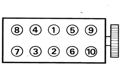
9.26a. Cylinder head bolt tightening sequence.
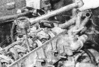
9.26b. Tighten the cylinder head bolts.
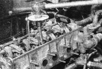
9.26s. Tighten the mounting bolts to the specified angle.
27. Install the rocker arm shaft and mounting plate, then reinsert the bolts and tighten them to the torque specified in the Specifications.
28. If the cylinder head has been rebuilt, it is recommended that the valve clearances be checked at this stage to eliminate any possibility of the valves touching the pistons after installing the timing belt. Turn the crankshaft so that none of the pistons are in the TDC position.
29. Install the thermostat as described in Section 3.
30. Install the toothed drive belt, see Chapter 5.
31. Adjust the valve clearances as described in Chapter 4.
32. Install the valve cover together with the new gasket and gradually tighten the mounting bolts.
33. Install the spark plugs if they were removed.
34. Install the high tension wire holder, then connect the wires to the spark plugs and secure them in the holder.
35. Connect the crankcase ventilation and cooling system hoses.
36. Install the intake and exhaust manifolds as described in Section 4B. Connect the exhaust outlet pipe.
37. Connect the gas pedal cable and adjust it as described in Section 4B.
38. Connect all wires.
39. If necessary, install the air filter as described in Section 4B.
40. Fill the engine with oil as described in Section 1.
41. Connect the positive and negative cables to the battery.
42. Fill and bleed the cooling system as described in Section 1.