



Removal
1. Remove the cylinder head as described in Chapter 9, and place it on the workbench.
2. Gradually loosen the bolts holding the rocker arm shaft and mounting plate to the cylinder head and remove the shaft. Please note that the bolts are not all the same and their locations must be marked before removal. Bolts #2 and #4 are solid, while the others are hollow. Their heads are color-coded accordingly (see illustrations).
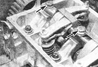
8.2a. Two rocker arm axle mounting bolts (marked with arrows).
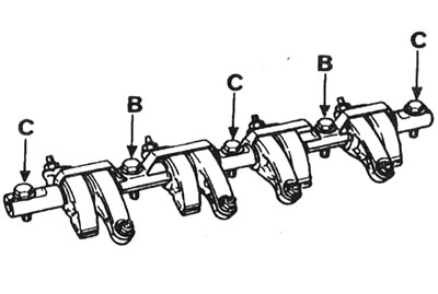
8.2b. Rocker arm axle mounting bolt designations: B - Solid bolts with yellow mark; C - Hollow bolts with black mark.
3. Holding the camshaft with a wrench by the special splines, unscrew the bolt and remove the sprocket (see illustration).
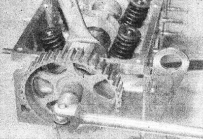
8.3. Unscrew the camshaft sprocket mounting bolt.
4. Using a socket wrench, unscrew the two bolts and remove the distributor from the cylinder head. There is no need to mark the installation position of the distributor.
5. Using a micrometer, measure the axial clearance of the camshaft and compare it with the data in Specifications (see illustration).
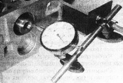
8.5. Using a micrometer, check the axial play of the camshaft.
In this way, the wear of the support plate can be determined.
6. Unscrew the two bolts and remove the support plate from the groove in the camshaft (see illustration).
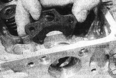
8.6. Remove the camshaft support plate.
7. Carefully remove the camshaft from the cylinder head on the sprocket side. Be careful not to damage the work surfaces (see illustration).
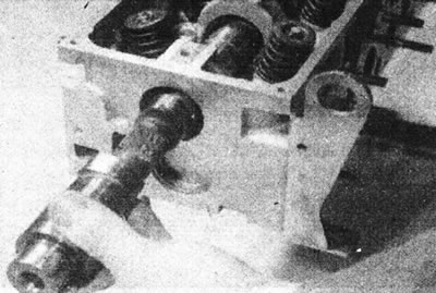
8.7. Remove the camshaft from the cylinder head.
Inspection
8. Inspect the working surfaces of the camshaft bearings, the working surfaces of the cams and the eccentric screw of the fuel pump for worn areas and scratches. Replace the camshaft if such damage is found.
9. Check the condition of the bearing surfaces on the camshaft and in the cylinder head. If these surfaces are excessively worn, a new head will be required.
Installation
10. Apply grease to the bearing surfaces in the cylinder head and to the camshaft lobes, then insert the camshaft into the head.
11. Install the support plate, then insert and tighten the bolts.
12. Measure the axial clearance as described in step 5 and ensure that it is within the limits given in Specifications limit values. Excessive axial clearance can only be caused by wear of the backing plate or camshaft.
13. Install the distributor and tighten the two bolts using a socket wrench.
14. Install the camshaft sprocket. Lock the camshaft, then insert and tighten the bolt to the torque specified in the Specifications(see illustration).
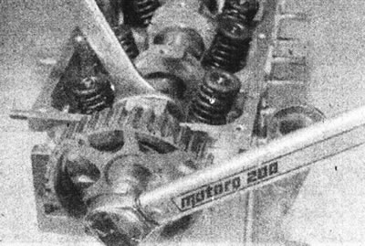
8.14. Tighten the camshaft mounting bolt.
15. Install the rocker arm shaft and mounting plate, then insert the bolts back into place and tighten them to the specified tightening torque Specifications.
16. Install the cylinder head as described in Chapter 9.