



Note: This action is not part of the maintenance procedures. This should only be done if valve mechanism noise is detected, or if there is a suspicion that power is being lost due to incorrect valve clearances. A new valve cover gasket may be required.
1. Remove the air filter as described in Section 4B.
2. Disconnect the accelerator pedal cable from the throttle body housing as described in Section 4B.
3. Disconnect the crankcase ventilation hoses from the valve cover.
4. Unscrew and remove the valve cover and gasket.
5. To make the engine easier to turn over, remove the spark plugs as described in Section 1.
6. Draw the position of the valves on a piece of paper, numbering them from the flywheel and labeling the inlet and outlet according to the cylinders (those. 1I, 1E, 2I, 2E, ZE, 3I, 4E, 4I). The intake valves are located on the intake manifold side and the exhaust valves are located on the exhaust manifold side. After adjusting the clearance of the corresponding valve, cross it out on paper.
7. Turn the crankshaft clockwise until the exhaust valve of cylinder No. 1 is fully open (that is, the valve spring will be fully compressed).
8. Insert the feeler gauge of the correct thickness (see Specifications) between the intake valve stem of cylinder No. 3 and the end of the rocker arm. If adjustment is necessary, loosen the rocker arm locknut using a socket wrench and turn the adjustment screw with a small open-end wrench or pliers until the correct clearance is achieved. While holding the adjustment screw, tighten the lock nut (it is recommended to use a torque wrench to avoid distorting the screw threads) and recheck the adjustment, then repeat the adjustment procedure on the exhaust valve of cylinder #4. Note that the clearances for the intake and exhaust valves are different.
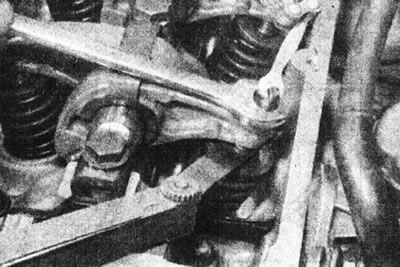
4.8. Adjusting the valve clearance.
9. Turn the crankshaft clockwise until exhaust valve No. 3 is fully open. Adjust the clearances of intake valve #4 and exhaust valve #2. Continue adjusting the valve clearances in the following sequence.
| Graduation is completely open | Adjustable | |
| inlet | outlet | |
| 1E | 3I | 4E |
| ZE | 4I | 2E |
| 4E | 2I | 1E |
| 2E | 1I | ZE |
10. Remove the socket or wrench from the crankshaft pulley bolt.
11. Before installing the valve cover, ensure that the spring clips are properly engaged in the grooves at each end of the rocker arm shaft.
12. Connect and adjust the accelerator pedal cable as described in Section 4B.
13. Install the air filter.